Page 224 of 456 Cabling Common Equipment in a Multi Group system
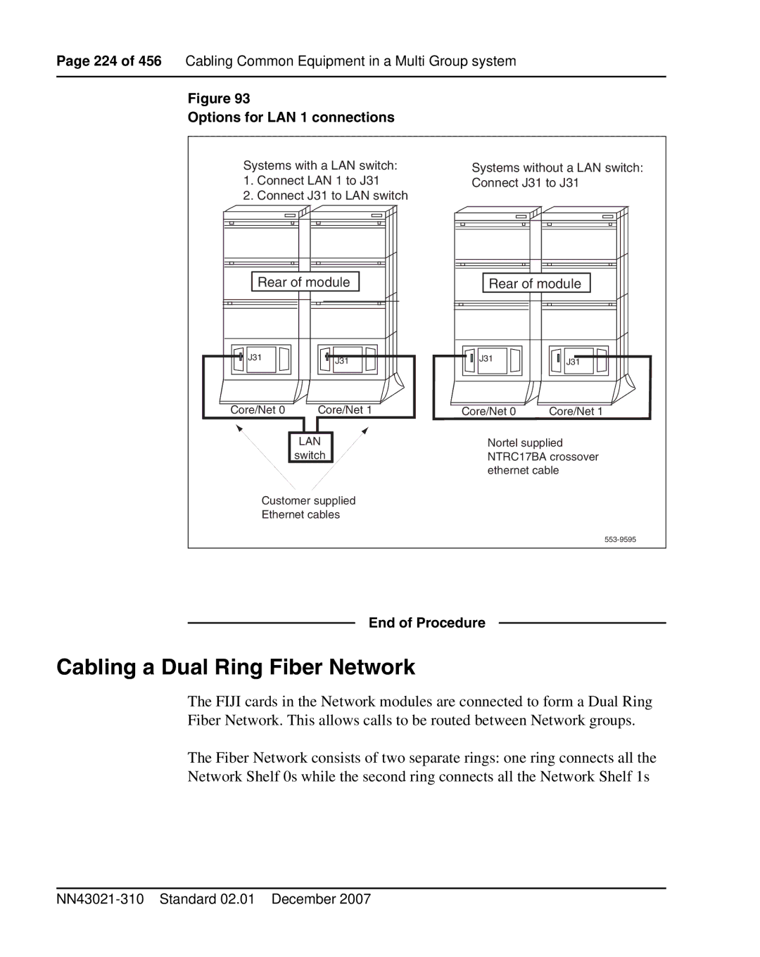
Figure 93
Options for LAN 1 connections
Systems with a LAN switch:
1.Connect LAN 1 to J31
2.Connect J31 to LAN switch
Rear of module | |
J31 | J31 |
| |
Core/Net 0 | Core/Net 1 |
LAN |
switch |
Customer supplied
Ethernet cables
Systems without a LAN switch: Connect J31 to J31
Rear of module |
J31 | J31 |
|
Core/Net 0 | Core/Net 1 |
Nortel supplied NTRC17BA crossover ethernet cable
End of Procedure
Cabling a Dual Ring Fiber Network
The FIJI cards in the Network modules are connected to form a Dual Ring Fiber Network. This allows calls to be routed between Network groups.
The Fiber Network consists of two separate rings: one ring connects all the Network Shelf 0s while the second ring connects all the Network Shelf 1s