Configuring the system monitor Page 165 of 456
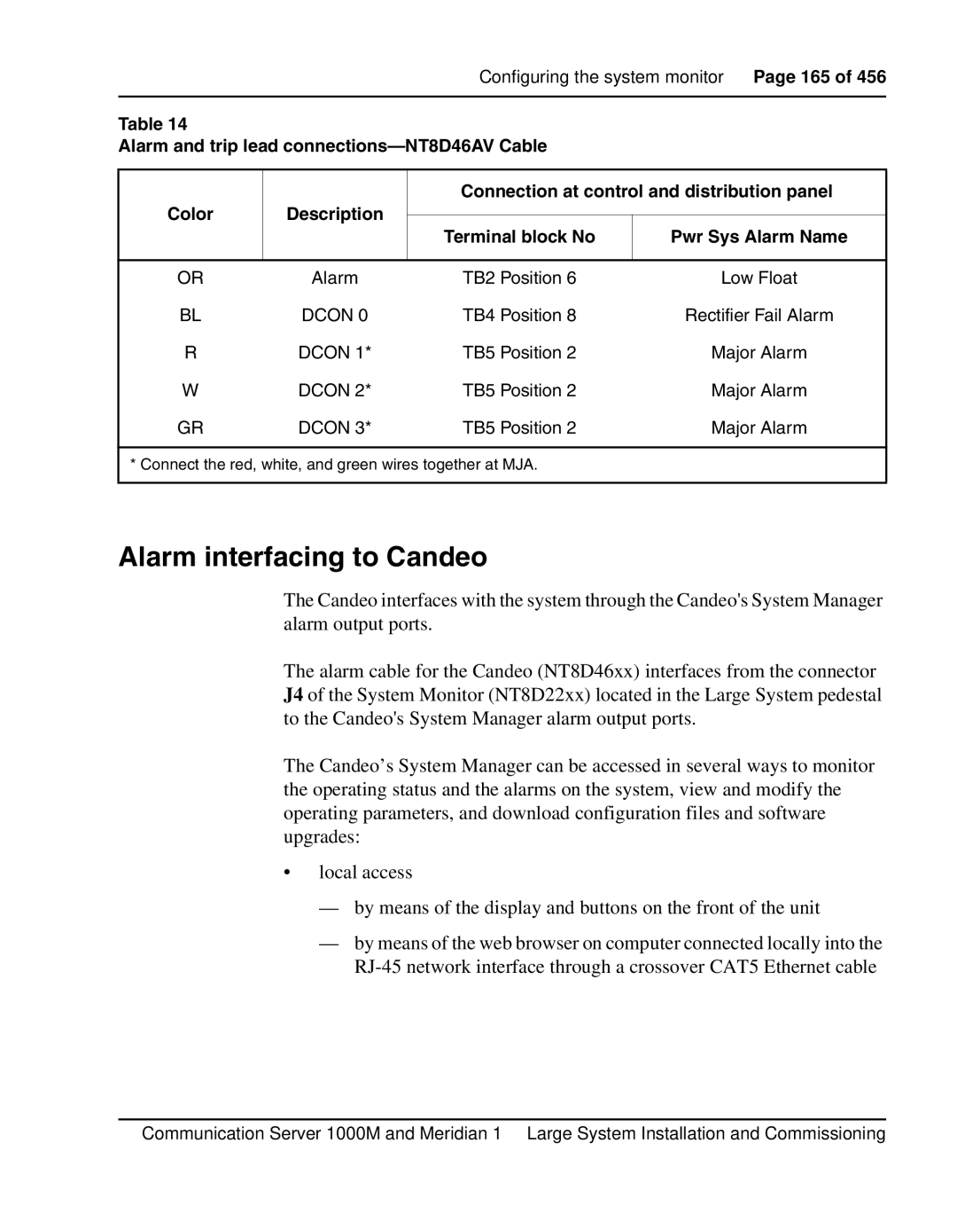
Table 14
Alarm and trip lead
|
| Connection at control and distribution panel | ||
Color | Description |
|
| |
Terminal block No | Pwr Sys Alarm Name | |||
|
| |||
|
|
|
| |
OR | Alarm | TB2 Position 6 | Low Float | |
BL | DCON 0 | TB4 Position 8 | Rectifier Fail Alarm | |
R | DCON 1* | TB5 Position 2 | Major Alarm | |
W | DCON 2* | TB5 Position 2 | Major Alarm | |
GR | DCON 3* | TB5 Position 2 | Major Alarm | |
* Connect the red, white, and green wires together at MJA.
Alarm interfacing to Candeo
The Candeo interfaces with the system through the Candeo's System Manager alarm output ports.
The alarm cable for the Candeo (NT8D46xx) interfaces from the connector J4 of the System Monitor (NT8D22xx) located in the Large System pedestal to the Candeo's System Manager alarm output ports.
The Candeo’s System Manager can be accessed in several ways to monitor the operating status and the alarms on the system, view and modify the operating parameters, and download configuration files and software upgrades:
•local access
—by means of the display and buttons on the front of the unit
—by means of the web browser on computer connected locally into the
Communication Server 1000M and Meridian 1 Large System Installation and Commissioning