Page 168 of 456 Configuring the system monitor
Table 16
Cable lengths
Cable | Length |
|
|
NT8D46AV | 9.75 m (32 ft) |
|
|
NT8D46BV | 19.5 m (64 ft) |
|
|
NT8D46CV | 30 m (100 ft) |
|
|
Cabling the Candeo
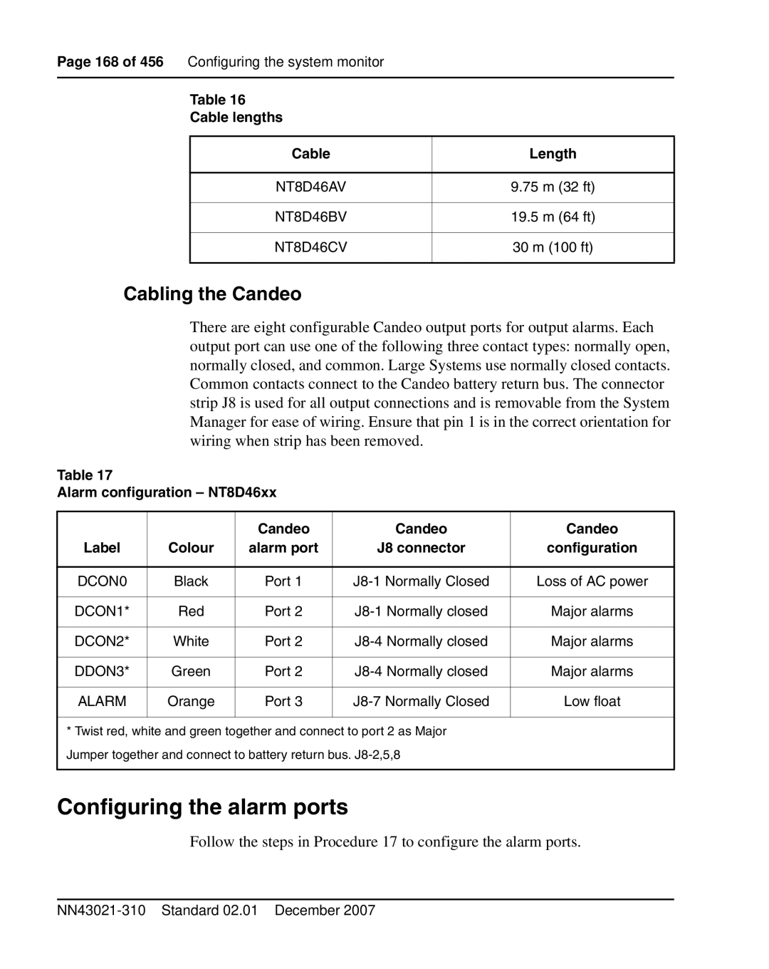
There are eight configurable Candeo output ports for output alarms. Each output port can use one of the following three contact types: normally open, normally closed, and common. Large Systems use normally closed contacts. Common contacts connect to the Candeo battery return bus. The connector strip J8 is used for all output connections and is removable from the System Manager for ease of wiring. Ensure that pin 1 is in the correct orientation for wiring when strip has been removed.
Table 17
Alarm configuration – NT8D46xx
|
| Candeo | Candeo | Candeo |
Label | Colour | alarm port | J8 connector | configuration |
|
|
|
|
|
DCON0 | Black | Port 1 | Loss of AC power | |
|
|
|
|
|
DCON1* | Red | Port 2 | Major alarms | |
|
|
|
|
|
DCON2* | White | Port 2 | Major alarms | |
|
|
|
|
|
DDON3* | Green | Port 2 | Major alarms | |
|
|
|
|
|
ALARM | Orange | Port 3 | Low float | |
|
|
|
|
|
* Twist red, white and green together and connect to port 2 as Major Jumper together and connect to battery return bus.
Configuring the alarm ports
Follow the steps in Procedure 17 to configure the alarm ports.
