Cabling Common Equipment in a Multi Group system Page 225 of 456
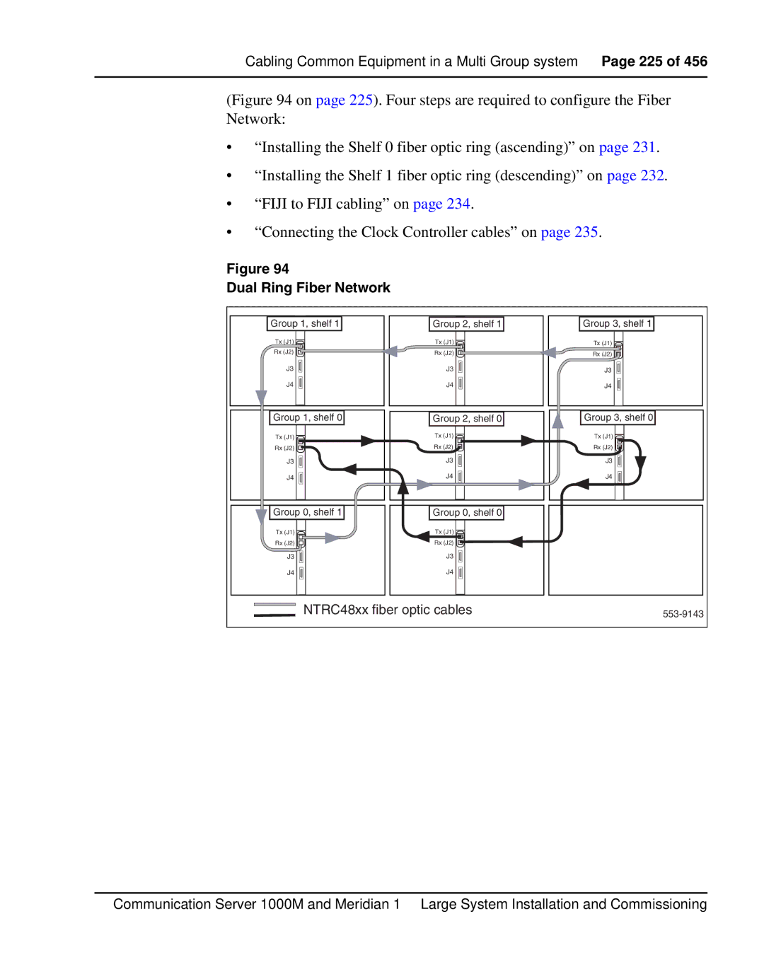
(Figure 94 on page 225). Four steps are required to configure the Fiber Network:
•“Installing the Shelf 0 fiber optic ring (ascending)” on page 231.
•“Installing the Shelf 1 fiber optic ring (descending)” on page 232.
•“FIJI to FIJI cabling” on page 234.
•“Connecting the Clock Controller cables” on page 235.
Figure 94
Dual Ring Fiber Network
Group 1, shelf 1 | Group 2, shelf 1 | Group 3, shelf 1 |
Tx (J1) | Tx (J1) | Tx (J1) |
Rx (J2) | Rx (J2) | Rx (J2) |
J3 | J3 | J3 |
J4 | J4 | J4 |
Group 1, shelf 0 | Group 2, shelf 0 | Group 3, shelf 0 |
Tx (J1) | Tx (J1) | Tx (J1) |
Rx (J2) | Rx (J2) | Rx (J2) |
J3 | J3 | J3 |
J4 | J4 | J4 |
Group 0, shelf 1 | Group 0, shelf 0 |
|
Tx (J1) | Tx (J1) |
|
Rx (J2) | Rx (J2) |
|
J3 | J3 |
|
J4 | J4 |
|
NTRC48xx fiber optic cables | ||
Communication Server 1000M and Meridian 1 Large System Installation and Commissioning