Page 140 of 456 Planning and designating a Main Distribution Frame
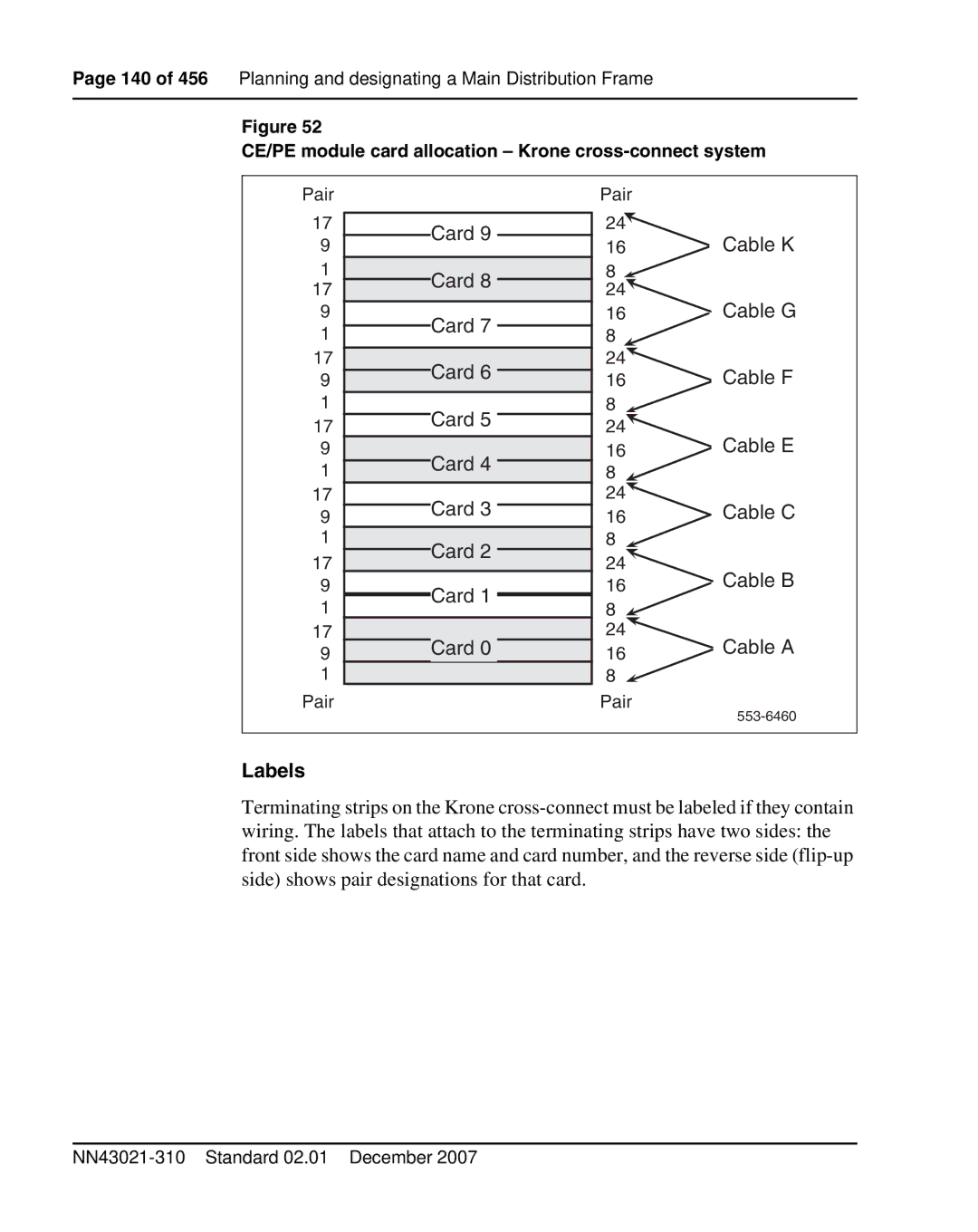
Figure 52
CE/PE module card allocation – Krone cross-connect system
Pair
17
9
1
17
9
1
17
9
1
17
9
1
17
9
1
17
9
1
17
9
1 Pair
Card 9
Card 8
Card 7
Card 6
Card 5
Card 4
Card 3
Card 2
Card 1
Card 0
Pair
24
16Cable K
8![]()
24![]()
16Cable G
8![]()
24
16Cable F
8![]()
24
16Cable E
8![]()
24![]()
16Cable C
8![]()
24
16Cable B
8 ![]()
24
16Cable A
8![]()
Pair
Labels
Terminating strips on the Krone
