Installing Power Failure Transfer Units Page 147 of 456
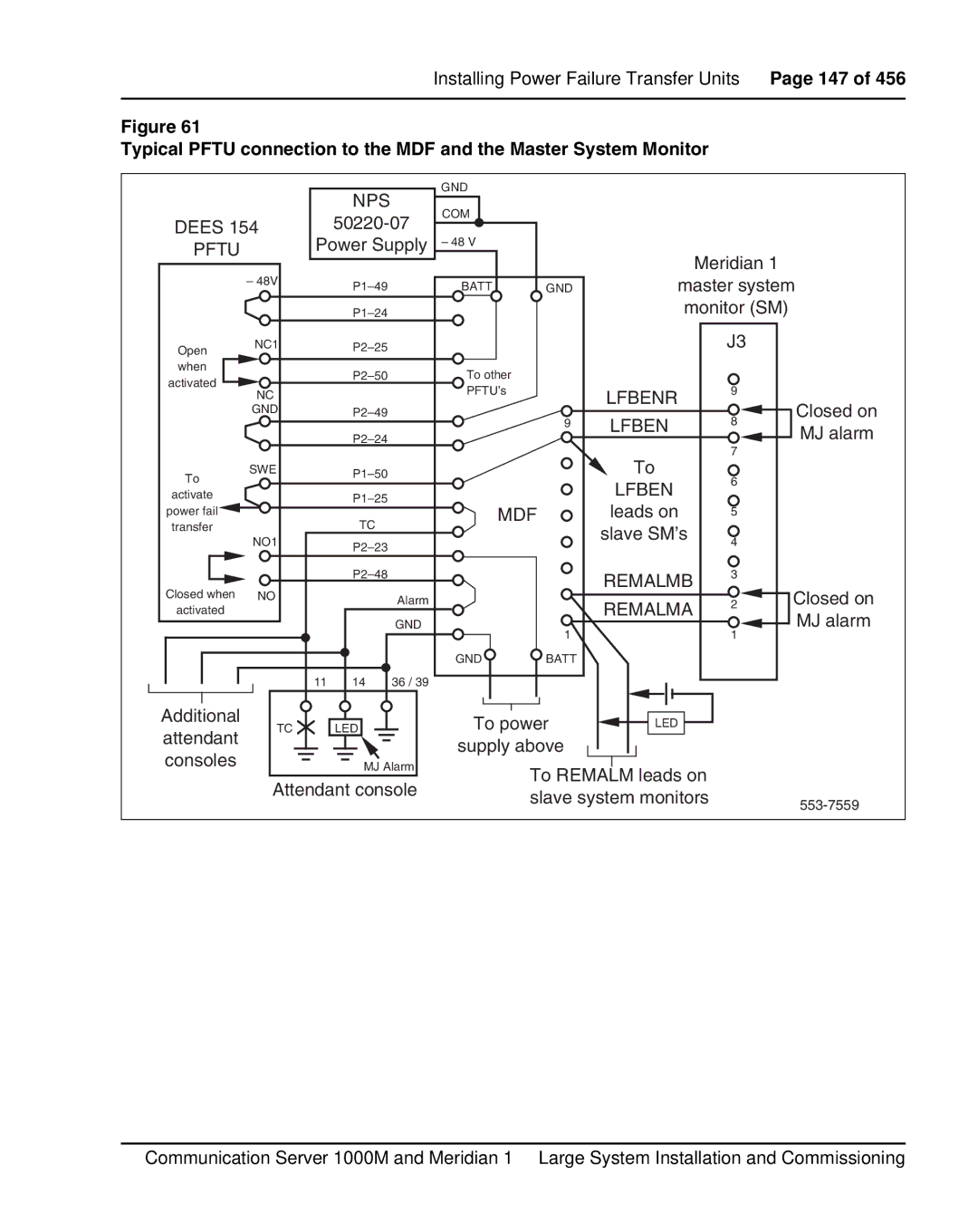
Figure 61
Typical PFTU connection to the MDF and the Master System Monitor
|
|
| NPS |
| GND |
|
|
|
|
|
|
|
| COM |
|
|
|
| |
DEES 154 |
|
|
|
|
| ||||
|
|
|
|
|
| ||||
PFTU |
| Power Supply | – 48 V |
| Meridian 1 |
| |||
|
|
|
|
|
|
|
| ||
| – 48V |
|
| BATT | GND | master system | |||
|
|
|
| ||||||
|
|
|
|
|
| monitor (SM) |
| ||
Open | NC1 |
|
|
|
|
| J3 |
| |
|
|
|
|
|
|
|
| ||
when |
|
|
| To other |
|
|
|
| |
activated |
|
|
|
|
|
|
| ||
NC |
|
|
| PFTU’s |
| LFBENR | 9 |
| |
|
|
|
|
|
| ||||
|
|
|
|
|
|
| Closed on | ||
| GND |
|
|
| 9 | LFBEN | 8 | ||
|
|
|
|
|
| MJ alarm | |||
|
|
|
|
|
| ||||
|
|
|
|
|
|
| 7 | ||
|
|
|
|
|
|
| To |
| |
To | SWE |
|
|
|
| 6 |
| ||
|
|
|
|
|
| LFBEN |
| ||
activate |
|
|
|
|
|
|
| ||
power fail |
|
|
| MDF | leads on | 5 |
| ||
|
| TC |
|
| |||||
transfer |
|
|
|
|
| slave SM’s |
|
| |
| NO1 |
|
|
|
| 4 |
| ||
|
|
|
|
|
|
| |||
|
|
|
|
|
|
|
|
| |
|
|
|
|
|
| REMALMB | 3 |
| |
Closed when | NO |
|
|
|
|
|
| Closed on | |
|
| Alarm |
|
| REMALMA | 2 | |||
activated |
|
|
|
|
| ||||
|
|
| GND |
|
|
| MJ alarm | ||
|
|
|
|
| 1 |
| 1 | ||
|
|
|
|
|
|
|
| ||
|
|
|
|
| GND | BATT |
|
|
|
|
| 11 | 14 | 36 / 39 |
|
|
|
|
|
Additional | TC |
| LED |
| To power | LED |
|
| |
attendant |
|
|
|
| |||||
|
|
|
| supply above |
|
|
| ||
consoles |
|
|
|
|
|
|
| ||
|
| MJ Alarm |
| To REMALM leads on |
|
| |||
| Attendant console |
|
|
| |||||
|
| slave system monitors |
| ||||||
|
|
|
|
|
|
| |||
|
|
|
|
|
|
|
|
| |
Communication Server 1000M and Meridian 1 Large System Installation and Commissioning