Page 84 of 456 Installing AC power
5Place a warning tag on the connection at the ground source. The warning tag should read
6Using a volt/ohm meter, measure the resistance between the ground pin on the power plug and the ground terminal on the power outlet.
7The resistance should be 0 ohms. If the resistance is greater than
0.5 ohms, check the power outlet ground and safety ground/protective earth connections.
8Remove the PDU field wiring access plate.
9Connect the logic return wire.
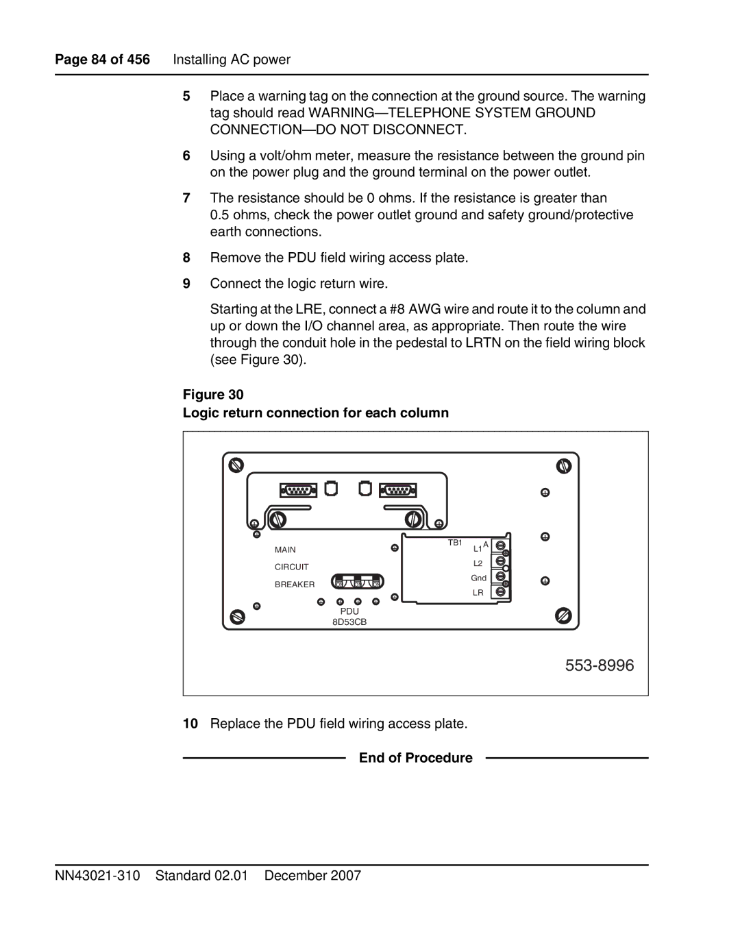
Starting at the LRE, connect a #8 AWG wire and route it to the column and up or down the I/O channel area, as appropriate. Then route the wire through the conduit hole in the pedestal to LRTN on the field wiring block (see Figure 30).
Figure 30
Logic return connection for each column
|
|
|
|
|
|
|
| + |
+ |
|
|
|
|
| + |
|
|
+ |
|
|
|
| + | TB1 | L1A | + |
| MAIN |
|
|
|
| |||
|
|
|
|
|
| |||
| CIRCUIT |
|
|
|
|
| L2 |
|
|
|
|
|
|
|
|
| |
| BREAKER | ON | ON | ON |
|
| Gnd | + |
|
|
| LR | |||||
| + | + | + | + | + |
|
| |
+ |
|
|
| |||||
|
|
|
| |||||
| PDU |
|
|
|
|
| ||
|
|
|
|
|
|
| ||
|
| 8D53CB |
|
|
|
|
| |
553-8996
10Replace the PDU field wiring access plate.