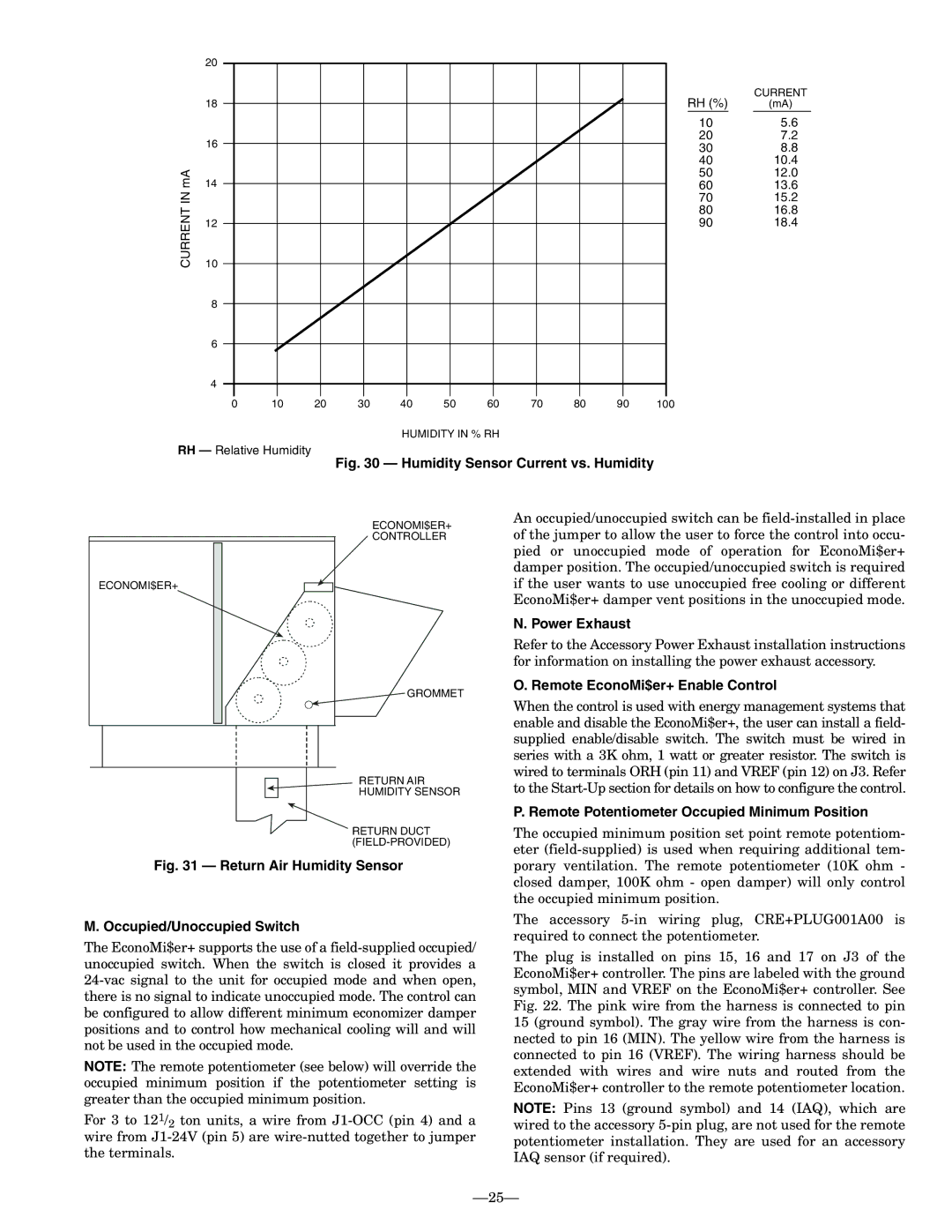
CURRENT IN mA

20


RH (%)


CURRENT


18


(mA)


10


5.6

16


20

7.2


30

8.8


40

10.4

14


50

12.0


60

13.6


70

15.2


80

16.8

12


90

18.4


10


8


6


4


0

10

20

30

40

50

60

70

80

90

100


HUMIDITY IN % RH

RH — Relative Humidity

Fig. 30 — Humidity Sensor Current vs. Humidity

ECONOMI$ER+

ECONOMI$ER+

CONTROLLER

GROMMET

RETURN AIR

HUMIDITY SENSOR

RETURN DUCT (FIELD-PROVIDED)

An occupied/unoccupied switch can be field-installed in place of the jumper to allow the user to force the control into occu- pied or unoccupied mode of operation for EconoMi$er+ damper position. The occupied/unoccupied switch is required if the user wants to use unoccupied free cooling or different EconoMi$er+ damper vent positions in the unoccupied mode.

N. Power Exhaust

Refer to the Accessory Power Exhaust installation instructions for information on installing the power exhaust accessory.

O. Remote EconoMi$er+ Enable Control

When the control is used with energy management systems that enable and disable the EconoMi$er+, the user can install a field- supplied enable/disable switch. The switch must be wired in series with a 3K ohm, 1 watt or greater resistor. The switch is wired to terminals ORH (pin 11) and VREF (pin 12) on J3. Refer to the Start-Up section for details on how to configure the control.

P. Remote Potentiometer Occupied Minimum Position

The occupied minimum position set point remote potentiom- eter (field-supplied) is used when requiring additional tem-

Fig. 31 — Return Air Humidity Sensor

M. Occupied/Unoccupied Switch

The EconoMi$er+ supports the use of a field-supplied occupied/ unoccupied switch. When the switch is closed it provides a 24-vac signal to the unit for occupied mode and when open, there is no signal to indicate unoccupied mode. The control can be configured to allow different minimum economizer damper positions and to control how mechanical cooling will and will not be used in the occupied mode.

NOTE: The remote potentiometer (see below) will override the occupied minimum position if the potentiometer setting is greater than the occupied minimum position.

For 3 to 121/2 ton units, a wire from J1-OCC (pin 4) and a wire from J1-24V (pin 5) are wire-nutted together to jumper the terminals.

porary ventilation. The remote potentiometer (10K ohm - closed damper, 100K ohm - open damper) will only control the occupied minimum position.

The accessory 5-in wiring plug, CRE+PLUG001A00 is required to connect the potentiometer.

The plug is installed on pins 15, 16 and 17 on J3 of the EconoMi$er+ controller. The pins are labeled with the ground symbol, MIN and VREF on the EconoMi$er+ controller. See Fig. 22. The pink wire from the harness is connected to pin 15 (ground symbol). The gray wire from the harness is con- nected to pin 16 (MIN). The yellow wire from the harness is connected to pin 16 (VREF). The wiring harness should be extended with wires and wire nuts and routed from the EconoMi$er+ controller to the remote potentiometer location.

NOTE: Pins 13 (ground symbol) and 14 (IAQ), which are wired to the accessory 5-pin plug, are not used for the remote potentiometer installation. They are used for an accessory IAQ sensor (if required).

25

Page 25
Image 25
Bryant 580F Power Exhaust, Remote EconoMi$er+ Enable Control, Remote Potentiometer Occupied Minimum Position

580F specifications

The Bryant 580F is a highly regarded gas furnace known for its exceptional heating performance and advanced technology. Designed for residential use, this model stands out for its reliability, efficiency, and user-friendly features that cater to modern heating demands.

One of the most notable features of the Bryant 580F is its efficiency rating. With an AFUE (Annual Fuel Utilization Efficiency) rating of up to 95%, this furnace maximizes heat output while minimizing energy consumption. This high level of efficiency not only results in lower utility bills but also reduces the environmental impact—a critical consideration for today’s eco-conscious homeowners.

The Bryant 580F is equipped with a multi-speed blower that ensures consistent airflow and enhances comfort by maintaining even temperatures throughout the home. This technology allows the furnace to adjust its operation based on the heating needs, leading to quieter operation and increased comfort levels.

In terms of construction, the Bryant 580F is built with durable materials that promise longevity and resilience against wear and tear. Its compact design makes installation easier, allowing it to fit into tight spaces without compromising its performance.

One of the standout technologies integrated into the Bryant 580F is its enhanced control system. The furnace works seamlessly with smart thermostats, allowing homeowners to monitor and adjust heating settings from their mobile devices. This feature not only provides convenience but also allows for energy-saving optimizations based on personal schedules and preferences.

Safety is also a primary concern with the Bryant 580F. It includes robust safety features such as a hot surface ignition system that eliminates the need for a standing pilot light, reducing the risk of gas leaks. Additionally, advanced diagnostics help in troubleshooting and maintenance, ensuring that potential issues can be identified and resolved quickly.

In conclusion, the Bryant 580F gas furnace is a remarkable choice for those seeking a blend of efficiency, comfort, and advanced technology. Its high AFUE rating, multi-speed blower, smart control compatibility, and safety features make it a reliable option for homeowners looking to invest in a dependable heating solution. As the demand for energy-efficient heating continues to grow, the Bryant 580F stands out as a model that meets and exceeds expectations in the modern heating landscape.