The unoccupied minimum position can only be set at the con- troller. The occupied minimum position set point configured at the EconoMi$er+ controller should be set to 0 when using a remote potentiometer. The occupied minimum position will also be used as part of the IAQ routing; it will be the maximum position the damper moves to when there is an IAQ call.
If the remote potentiometer (occupied) position is greater than the EconoMi$er+ controller unoccupied minimum posi- tion, then the remote potentiometer setting will be used. The remote potentiometer is field supplied and must be a 3-wire, linear potentiometer with a resistance between 10K ohm and 100K ohm (such as the Honeywell S963B1128).
Q. Demand Ventilation Control
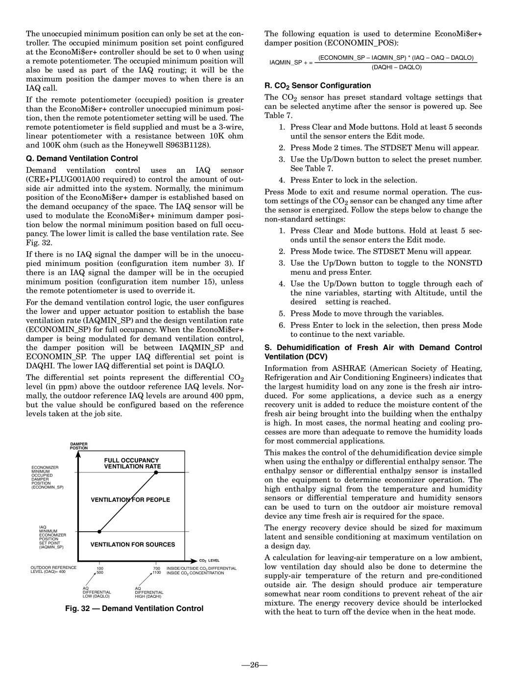
Demand ventilation control uses an IAQ sensor (CRE+PLUG001A00 required) to control the amount of out- side air admitted into the system. Normally, the minimum position of the EconoMi$er+ damper is established based on the demand occupancy of the space. The IAQ sensor will be used to modulate the EconoMi$er+ minimum damper posi- tion below the normal minimum position based on full occu- pancy. The lower limit is called the base ventilation rate. See Fig. 32.
If there is no IAQ signal the damper will be in the unoccu- pied minimum position (configuration item number 3). If there is an IAQ signal the damper will be in the occupied minimum position (configuration item number 15), unless the remote potentiometer is used to override it.
For the demand ventilation control logic, the user configures the lower and upper actuator position to establish the base ventilation rate (IAQMIN_SP) and the design ventilation rate (ECONOMIN_SP) for full occupancy. When the EconoMi$er+ damper is being modulated for demand ventilation control, the damper position will be between IAQMIN_SP and ECONOMIN_SP. The upper IAQ differential set point is DAQHI. The lower IAQ differential set point is DAQLO.
The differential set points represent the differential CO2 level (in ppm) above the outdoor reference IAQ levels. Nor- mally, the outdoor reference IAQ levels are around 400 ppm, but the value should be configured based on the reference levels taken at the job site.
| DAMPER | | | |
| POSTION | | | |
| | | FULL OCCUPANCY | |
| ECONOMIZER | | VENTILATION RATE | |
| MINIMUM | | | |
| OCCUPIED | | | |
| DAMPER | | | |
| POSITION | | | |
| (ECONOMIN_SP) | | | |
| | VENTILATION FOR PEOPLE |
| IAQ | | | |
| MINIMUM | | | |
| ECONOMIZER | | | |
| POSITION | | | |
| SET POINT | VENTILATION FOR SOURCES |
| (IAQMIN_SP) |
| | | |
| | | | CO2 LEVEL |
| OUTDOOR REFERENCE | 100 | 700 | INSIDE/OUTSIDE CO2 DIFFERENTIAL |
| LEVEL (OAQ)= 400 | 500 | 1100 | INSIDE CO2 CONCENTRATION |
AQ | AQ |
DIFFERENTIAL | DIFFERENTIAL |
LOW (DAQLO) | HIGH (DAQHI) |
Fig. 32 — Demand Ventilation Control
The following equation is used to determine EconoMi$er+ damper position (ECONOMIN_POS):
(ECONOMIN_SP – IAQMIN_SP) * (IAQ – OAQ – DAQLO)
IAQMIN_SP + =
(DAQHI – DAQLO)
R. CO2 Sensor Configuration
The CO2 sensor has preset standard voltage settings that can be selected anytime after the sensor is powered up. See Table 7.
1.Press Clear and Mode buttons. Hold at least 5 seconds until the sensor enters the Edit mode.
2.Press Mode 2 times. The STDSET Menu will appear.
3.Use the Up/Down button to select the preset number. See Table 7.
4.Press Enter to lock in the selection.
Press Mode to exit and resume normal operation. The cus- tom settings of the CO2 sensor can be changed any time after the sensor is energized. Follow the steps below to change the non-standard settings:
1.Press Clear and Mode buttons. Hold at least 5 sec- onds until the sensor enters the Edit mode.
2.Press Mode twice. The STDSET Menu will appear.
3.Use the Up/Down button to toggle to the NONSTD menu and press Enter.
4.Use the Up/Down button to toggle through each of
the nine variables, starting with Altitude, until the desired setting is reached.
5.Press Mode to move through the variables.
6.Press Enter to lock in the selection, then press Mode to continue to the next variable.
S.Dehumidification of Fresh Air with Demand Control Ventilation (DCV)
Information from ASHRAE (American Society of Heating, Refrigeration and Air Conditioning Engineers) indicates that the largest humidity load on any zone is the fresh air intro- duced. For some applications, a device such as a energy recovery unit is added to reduce the moisture content of the fresh air being brought into the building when the enthalpy is high. In most cases, the normal heating and cooling pro- cesses are more than adequate to remove the humidity loads for most commercial applications.
This makes the control of the dehumidification device simple when using the enthalpy or differential enthalpy sensor. The enthalpy sensor or differential enthalpy sensor is installed on the equipment to determine economizer operation. The high enthalpy signal from the temperature and humidity sensors or differential temperature and humidity sensors can be used to turn on the outdoor air moisture removal device any time fresh air is required for the space.
The energy recovery device should be sized for maximum latent and sensible conditioning at maximum ventilation on a design day.
A calculation for leaving-air temperature on a low ambient, low ventilation day should also be done to determine the supply-air temperature of the return and pre-conditioned outside air. The design should produce air temperature somewhat near room conditions to prevent reheat of the air mixture. The energy recovery device should be interlocked with the heat to turn off the device when in the heat mode.