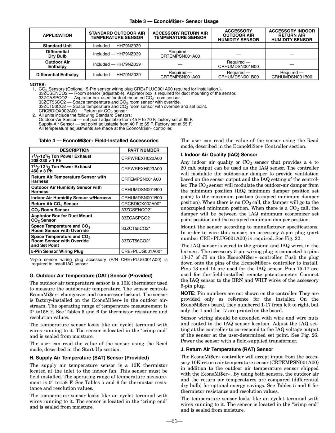
Bryant 580F EconoMi$er+ Sensor Usage, EconoMi$er+ Field-InstalledAccessories

Models: 580F

1 80
Download 80 pages 29.14 Kb
Page 21
Image 21

Table 3 — EconoMi$er+ Sensor Usage


STANDARD OUTDOOR AIR

ACCESSORY RETURN AIR

ACCESSORY

ACCESSORY INDOOR

APPLICATION

OUTDOOR AIR

RETURN AIR

TEMPERATURE SENSOR

TEMPERATURE SENSOR


HUMIDITY SENSOR

HUMIDITY SENSOR


Standard Unit

Included — HH79NZ039

Differential

Included — HH79NZ039

Required —

Dry Bulb

CRTEMPSN001A00


Outdoor Air

Included — HH79NZ039

Required —

Enthalpy

CRHUMDSN001B00


Differential Enthalpy

Included — HH79NZ039

Required —

Required —

Required —

CRTEMPSN001A00

CRHUMDSN001B00

CRHUMDSN001B00


NOTES:

1.CO2 Sensors (Optional, 5-Pin sensor wiring plug CRE+PLUG001A00 required for installation.).

33ZCSENCO2 — Room sensor (adjustable). Aspirator box is required for duct mounting of the sensor.

33ZCASPCO2 — Aspirator box used for duct-mounted CO2 room sensor.

33ZCT55CO2 — Space temperature and CO2 room sensor with override.

33ZCT56CO2 — Space temperature and CO2 room sensor with override and set point. CRCBDIOX002A00 — Return air CO2 sensor.

2.All units include the following Standard Sensors:

Outdoor-Air Sensor — set point adjustable from 45 F to 70 F, factory set at 65 F. Supply-Air Sensor — set point adjustable from 40 F to 65 F. Factory set at 55 F. All temperature adjustments are made at the EconoMi$er+ controller.

Table 4 — EconoMi$er+ Field-Installed Accessories


DESCRIPTION

PART NUMBER

71/ -121/

Ton Power Exhaust

CRPWREXH022A00

2

2

208-230 v 1 Ph


71/ -121/

Ton Power Exhaust

CRPWREXH023A00

2

2

460 v 3 Ph


Return Air Temperature Sensor with

CRTEMPSN001A00

Harness


Outdoor Air Humidity Sensor with

CRHUMDSN001B00

Harness


Indoor Air Humidity Sensor w/Harness

CRHUMDSN001B00

Return Air CO2 Sensor

CRCBDIOX002A00*

CO2 Room Sensor

33ZCSENCO2*

Aspirator Box for Duct Mount

33ZCASPCO2

CO2 Sensor


Space Temperature and CO2

33ZCT55CO2*

Room Sensor with Override


Space Temperature and CO2

33ZCT56CO2*

Room Sensor with Override

and Set Point


5-Pin Sensor Wiring Plug

CRE+PLUG001A00*

*5-pin sensor wiring plug accessory (P/N CRE+PLUG001A00) is required to install IAQ sensor.

G. Outdoor Air Temperature (OAT) Sensor (Provided)

The outdoor air temperature sensor is a 10K thermistor used to measure the outdoor-air temperature. The sensor controls EconoMi$er+ changeover and compressor lockout. The sensor is factory-installed on the EconoMi$er+ in the outdoor air- stream. The operating range of temperature measurement is 0° to158 F. See Tables 5 and 6 for thermistor resistance and resolution values.

The temperature sensor looks like an eyelet terminal with wires running to it. The sensor is located in the “crimp end” and is sealed from moisture.

The user can read the value of the sensor using the Read mode, described in the Start-Up section.

H. Supply Air Temperature (SAT) Sensor (Provided)

The supply air temperature sensor is a 10K thermistor located at the inlet to the indoor fan. This sensor must be field installed. The operating range of temperature measure- ment is 0° to158 F. See Tables 5 and 6 for thermistor resis- tance and resolution values.

The temperature sensor looks like an eyelet terminal with wires running to it. The sensor is located in the “crimp end” and is sealed from moisture.

The user can read the value of the sensor using the Read mode, described in the EconoMi$er+ Controller section.

I. Indoor Air Quality (IAQ) Sensor

Any indoor air quality or CO2 sensor that provides a 4 to 20 mA output can be used as the IAQ sensor. The controller will modulate the outdoor-air damper to provide ventilation based on the sensor output and the IAQ setting of the control- ler. The CO2 sensor will modulate the outdoor-air damper from the minimum position (IAQ minimum damper position set point) to the maximum position (occupied minimum damper position). When there is no CO2 call, the damper will go to the unoccupied minimum position. When there is a CO2 call, the damper will be between the IAQ minimum economizer set point position and the occupied minimum damper position.

Mount the sensor according to manufacturer specifications. In order to wire this sensor, an accessory 5-pin plug (part number CRE+PLUG001A00) is required. See Fig. 22.

The IAQ sensor is wired to the ground and IAQ wires in the harness. The accessory 5-pin wiring plug is connected to pins 13-17 of J3 on the EconoMi$er+ controller. Push the plug down onto the pins of the EconoMi$er+ controller to install. Pins 13 and 14 are used for the IAQ sensor. Pins 15-17 are used for the field-installed remote potentiometer. Connect the IAQ sensor to the BRN and WHT wires of the accessory 5-pin plug.

NOTE: Pin numbers are not shown on the controller. They are provided only as reference for the installer. On the EconoMi$er+ board, they numbered 1-17 from left to right, but only the 1 and the 17 are printed on the board.

Sensor wiring should be extended with wire and wire nuts and routed to the IAQ sensor location. Adjust the IAQ set- ting at the controller to correspond to the IAQ voltage output of the sensor at the user-determined set point. See Fig. 26. Power the sensor with a field-supplied transformer.

J. Return Air Temperature (RAT) Sensor

The EconoMi$er+ controller will accept input from the acces- sory 10K return air temperature sensor (CRTEMPSN001A00) in addition to the outdoor air temperature sensor shipped with the EconoMi$er+. By using both sensors, the outdoor air and the return air temperatures are compared (differential dry bulb) for optimal energy savings. See Tables 5 and 6 for thermistor resistance and resolution values.

The temperature sensor looks like an eyelet terminal with wires running to it. The sensor is located in the “crimp end” and is sealed from moisture.

21

Page 21
Image 21
Bryant 580F EconoMi$er+ Sensor Usage, EconoMi$er+ Field-InstalledAccessories, I. Indoor Air Quality IAQ Sensor