If the suction pressure does not drop and the discharge pres- sure does not rise to normal levels:
1.Note that the evaporator fan is probably also rotating in the wrong direction.
2.Turn off power to the unit and install lockout tag.
3.Reverse any two of the unit power leads.
4.Reapply power to unit. Reenergize compressor.
The suction and discharge pressure levels should now move to their normal start-up levels.
NOTE: When the compressor is rotating in the wrong direc- tion, the unit will make an elevated level of noise and will not provide cooling.
X. COOLING
To start unit, turn on main power supply. Set system selector switch at COOL position and fan switch at AUTO. position. Adjust thermostat to a setting below room temperature. Compressor, indoor and outdoor fans start on closure of contactors.
Check unit charge. Refer to Checking and Adjusting Refrigerant Charge section, page 62. Unit must operate a minimum of 10 minutes before adjusting charge.
Reset thermostat at a position above room temperature. Compressor and outdoor fans will shut off. Evaporator fan will shut off after 30-second delay.
A. To Shut Off Unit
Set system selector switch at OFF position. Resetting ther- mostat at a position above room temperature shuts unit off temporarily until space temperature exceeds thermostat setting.
XI. MAIN BURNERS
Main burners are factory set and should require no adjustment.
TO CHECK ignition of main burners and heating controls, move thermostat set point above room temperature and ver- ify that the burners light and evaporator fan is energized. After ensuring that the unit continues to heat the building, lower the thermostat setting below the room temperature and verify that the burners and evaporator fan turn off (fan will turn off only if fan selector switch is in the AUTO. posi- tion). Refer to Table 31 for the correct orifice to use at high altitudes.
NOTE: Upon a call for heat, the main burners will remain on for a minimum of 60 seconds.
A. Adjust Gas Input
The gas input to the unit is determined by measuring the gas flow at the meter or by measuring the manifold pressure. Manifold pressure should be 3.5 in. wg. in high-fire operation.
NOTE: Unit uses a 2-stage gas valve. There is no need to adjust the “Low Fire” manifold pressure.
Measure Gas Flow (Natural Gas Units)
Minor adjustment to the gas flow can be made by changing the manifold pressure. The manifold pressure must be
3.5in. wg. Normal manifold pressure is 3.5 in. wg in high fire (W1 and W2 inputs to gas valve).
Proceed as follows:
1.Turn off gas supply to unit.
2.Remove pipe plug on manifold then connect manome- ter at this point. Turn on gas to unit. Ensure gas valve is in high fire operation.
Observe manifold pressure in high fire (W1 and W2 ener- gized) and proceed as follows to adjust gas input:
1.Remove cover screw over regulator adjustment screw on gas valve. Ensure gas valve is operating in high fire mode.
2.Turn regulator adjustment screw clockwise to increase gas input, or turn regulator adjustment screw counterclockwise to decrease input. High fire manifold pressure must be 3.5 in. wg.
 WARNING: Unsafe operation of the unit may result if manifold pressure is outside 3.4 to 3.6 in. wg range. Personal injury or unit damage may result.
3.Replace cover screw cap on gas valve.
4.Turn off gas supply to unit. Remove manometer from pressure tap and replace pipe plug on gas valve. Turn on gas to unit and check for leaks.
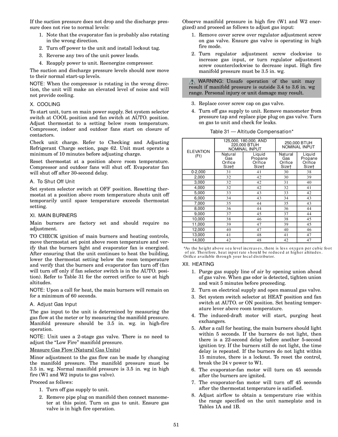
Table 31 — Altitude Compensation*
| | 125,000, 180,000, AND | 250,000 BTUH |
| | 220,000 BTUH |
| | NOMINAL INPUT |
| ELEVATION | NOMINAL INPUT |
| | |
| (Ft) | Natural | Liquid | Natural | Liquid |
| Gas | Propane | Gas | Propane |
| |
| | Orifice | Orifice | Orifice | Orifice |
| | Size† | Size† | Size† | Size† |
| 0-2,000 | 31 | 41 | 30 | 38 |
| 2,000 | 32 | 42 | 30 | 39 |
| 3,000 | 32 | 42 | 31 | 40 |
| 4,000 | 32 | 42 | 32 | 41 |
| 5,000 | 33 | 43 | 33 | 42 |
| 6,000 | 34 | 43 | 34 | 43 |
| 7,000 | 35 | 44 | 35 | 43 |
| 8,000 | 36 | 44 | 36 | 44 |
| 9,000 | 37 | 45 | 37 | 44 |
| 10,000 | 38 | 46 | 38 | 45 |
| 11,000 | 39 | 47 | 39 | 45 |
| 12,000 | 40 | 47 | 40 | 46 |
| 13,000 | 41 | 48 | 41 | 47 |
| 14,000 | 42 | 48 | 42 | 47 |
*As the height above sea level increases, there is less oxygen per cubic foot of air. Therefore, heat input rate should be reduced at higher altitudes.
†Orifice available through your local distributor.
XII. HEATING
1.Purge gas supply line of air by opening union ahead of gas valve. When gas odor is detected, tighten union and wait 5 minutes before proceeding.
2.Turn on electrical supply and open manual gas valve.
3.Set system switch selector at HEAT position and fan switch at AUTO. or ON position. Set heating temper- ature lever above room temperature.
4.The induced-draft motor will start, purging heat exchangers.
5.After a call for heating, the main burners should light within 5 seconds. If the burners do not light, then there is a 22-second delay before another 5-second ignition try. If the burners still do not light, the time delay is repeated. If the burners do not light within 15 minutes, there is a lockout. To reset the control, break the 24 v power to W1.
6.The evaporator-fan motor will turn on 45 seconds after the burners are ignited.
7.The evaporator-fan motor will turn off 45 seconds after the thermostat temperature is satisfied.
8.Adjust airflow to obtain a temperature rise within the range specified on the unit nameplate and in Tables 1A and 1B.