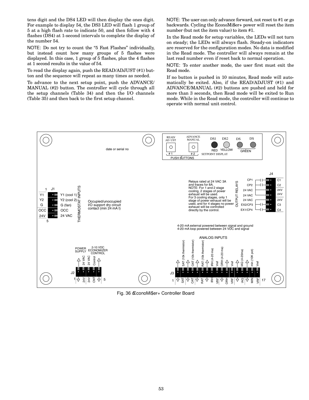
tens digit and the DS4 LED will then display the ones digit. For example to display 54, the DS3 LED will flash 1 group of 5 at a high flash rate to indicate 50, and then follow with 4 flashes (DS4) at 1-second intervals to complete the display of the number 54.

NOTE: Do not try to count the “5 Fast Flashes” individually, but instead count how many groups of 5 flashes were displayed. In this case, 1 group of 5 flashes, plus the 4 flashes at 1 second results in the value of 54.

To read the display again, push the READ/ADJUST (#1) but- ton and the sequence will repeat as many times as needed.

To advance to the next setup point, push the ADVANCE/ MANUAL (#2) button. The controller will cycle through all the setup channels (Table 34) and then the I/O channels (Table 35) and then back to the first setup channel.

date or serial no

NOTE: The user can only advance forward, not reset to #1 or go backwards. Cycling the EconoMi$er+ power will reset the item number (but not the item value) to item #1.

In the Read mode for setup variables, the LEDs will not turn on steady; the LEDs will always flash. Steady-on indicators are reserved for the configuration modes. No data is modified in the Read mode. The controller will always remain at the last read number even if reset back to normal operation.

NOTE: To enter another mode, the user first must exit the Read mode.

If no button is pushed in 10 minutes, Read mode will auto- matically be exited. Also, if the READ/ADJUST (#1) and ADVANCE/MANUAL (#2) buttons are pushed and held for more than 3 seconds, then Read mode will be exited to Run mode. While in the Read mode, the controller will continue to operate with normal unit control.

READ/

ADVANCE

DS1

DS2

DS3 DS4

ADJUST

MANUAL


# 1


RED

YELLOW

GREEN

# 2 SETPOINT DISPLAY


PUSH BUTTONS

1

J1

INPUTS


Y1 (cool 1)


Y1


Y2


Y2 (cool 2)

THERMOSTAT

Occupied/unoccupied

5


G


G (fan)


I/O support dry circuit


OCC


OCC


contact (min 24 mA I)


24 VAC


24V


POWER


2-10 VDC

ECONOMIZER

SUPPLY


CONTROL

24 VAC

24 VAC

Control

J2

24V

24V

CNT


1

5


Relays rated at 24 VAC 3A

RELAYS

CP1

24 VAC

cooling, 2 stages of power

and traces for 8A.


CP2

NOTE: For 1 and 2 stage


exhaust will be used.

OUTPUT

24 VAC

For 3 cooling stages, only 1


24 VAC

stage of power exhaust will be


used, and for 4 stages no power


EX2/CP3

exhaust will be controlled


directly by the control.


EX1/CP4

4-20 mA external powered between signal and ground 4-20 mA loop powered between 24 VDC and signal

ANALOG INPUTS

SAT (10k thermistor)

OAT (10k thermistor)

RAT (10k thermistor)

IRH (4-20 ma)

Vref

ORH (4-20 ma)

Vref

IAQ (4-20ma)

min (10K pot)

Vref

J3

1

SAT

OAT

RAT

IRH

VRF

ORH

VRF

IAQ

MIN

VRF


J4

C1

C2

24V

24V

24V

C3

C4

17

Fig. 36 — EconoMi$er+ Controller Board

53

Page 53
Image 53
Bryant 580F installation instructions EconoMi$er+ Controller Board, DS1 DS2 DS3 DS4

580F specifications

The Bryant 580F is a highly regarded gas furnace known for its exceptional heating performance and advanced technology. Designed for residential use, this model stands out for its reliability, efficiency, and user-friendly features that cater to modern heating demands.

One of the most notable features of the Bryant 580F is its efficiency rating. With an AFUE (Annual Fuel Utilization Efficiency) rating of up to 95%, this furnace maximizes heat output while minimizing energy consumption. This high level of efficiency not only results in lower utility bills but also reduces the environmental impact—a critical consideration for today’s eco-conscious homeowners.

The Bryant 580F is equipped with a multi-speed blower that ensures consistent airflow and enhances comfort by maintaining even temperatures throughout the home. This technology allows the furnace to adjust its operation based on the heating needs, leading to quieter operation and increased comfort levels.

In terms of construction, the Bryant 580F is built with durable materials that promise longevity and resilience against wear and tear. Its compact design makes installation easier, allowing it to fit into tight spaces without compromising its performance.

One of the standout technologies integrated into the Bryant 580F is its enhanced control system. The furnace works seamlessly with smart thermostats, allowing homeowners to monitor and adjust heating settings from their mobile devices. This feature not only provides convenience but also allows for energy-saving optimizations based on personal schedules and preferences.

Safety is also a primary concern with the Bryant 580F. It includes robust safety features such as a hot surface ignition system that eliminates the need for a standing pilot light, reducing the risk of gas leaks. Additionally, advanced diagnostics help in troubleshooting and maintenance, ensuring that potential issues can be identified and resolved quickly.

In conclusion, the Bryant 580F gas furnace is a remarkable choice for those seeking a blend of efficiency, comfort, and advanced technology. Its high AFUE rating, multi-speed blower, smart control compatibility, and safety features make it a reliable option for homeowners looking to invest in a dependable heating solution. As the demand for energy-efficient heating continues to grow, the Bryant 580F stands out as a model that meets and exceeds expectations in the modern heating landscape.