Removing and Replacing the Front Chassis Panels
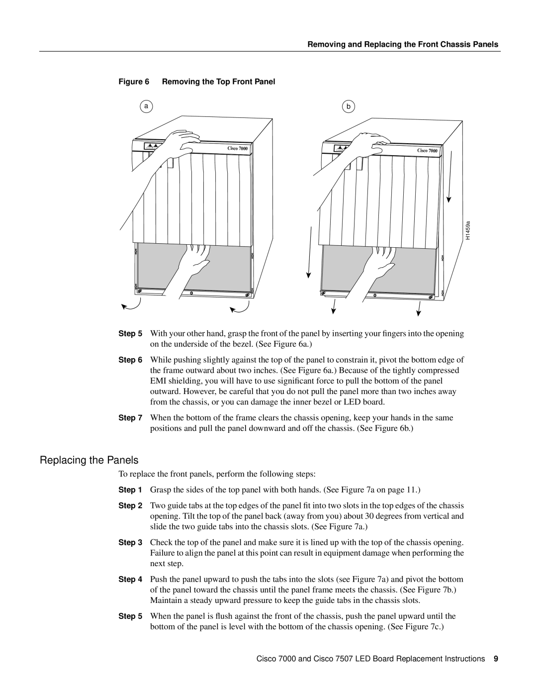
Figure 6 Removing the Top Front Panel
a |
|
| b |
|
|
| Cisco 7000 |
|
|
UPPER | LOWER | NORMAL |
|
|
POWER |
|
| ||
POWER | UPPER | LOWER | NORMAL | |
|
| POWER | POWER |
|
Cisco 7000 ![]()
H1459a
Step 5 With your other hand, grasp the front of the panel by inserting your fingers into the opening on the underside of the bezel. (See Figure 6a.)
Step 6 While pushing slightly against the top of the panel to constrain it, pivot the bottom edge of the frame outward about two inches. (See Figure 6a.) Because of the tightly compressed EMI shielding, you will have to use significant force to pull the bottom of the panel outward. However, be careful that you do not pull the panel more than two inches away from the chassis, or you can damage the inner bezel or LED board.
Step 7 When the bottom of the frame clears the chassis opening, keep your hands in the same positions and pull the panel downward and off the chassis. (See Figure 6b.)
Replacing the Panels
To replace the front panels, perform the following steps:
Step 1 Grasp the sides of the top panel with both hands. (See Figure 7a on page 11.)
Step 2 Two guide tabs at the top edges of the panel fit into two slots in the top edges of the chassis opening. Tilt the top of the panel back (away from you) about 30 degrees from vertical and slide the two guide tabs into the chassis slots. (See Figure 7a.)
Step 3 Check the top of the panel and make sure it is lined up with the top of the chassis opening. Failure to align the panel at this point can result in equipment damage when performing the next step.
Step 4 Push the panel upward to push the tabs into the slots (see Figure 7a) and pivot the bottom of the panel toward the chassis until the panel frame meets the chassis. (See Figure 7b.) Maintain a steady upward pressure to keep the guide tabs in the chassis slots.
Step 5 When the panel is flush against the front of the chassis, push the panel upward until the bottom of the panel is level with the bottom of the chassis opening. (See Figure 7c.)
Cisco 7000 and Cisco 7507 LED Board Replacement Instructions 9