Chapter 2 Interoperability and Performance Planning
Specifications
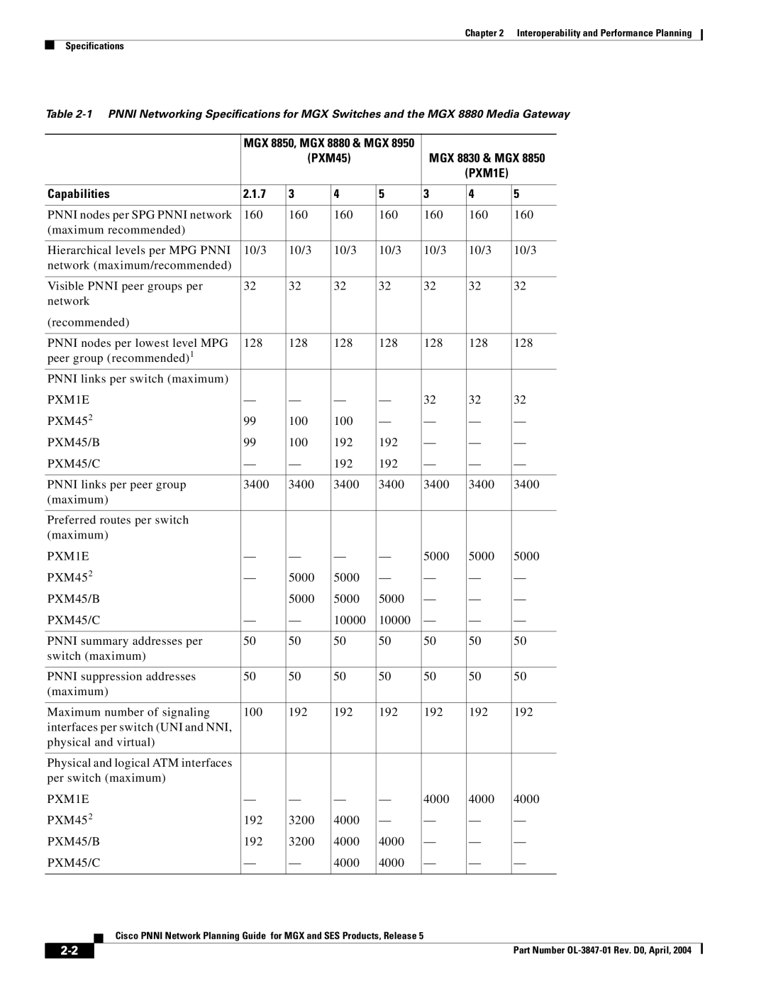
Table
|
|
|
| MGX 8850, MGX 8880 & MGX 8950 |
|
|
|
|
|
| |||
|
|
|
|
| (PXM45) |
| MGX 8830 & MGX 8850 | ||||||
|
|
|
|
|
|
|
|
| (PXM1E) |
|
|
| |
|
|
|
|
|
|
|
|
|
|
|
| ||
| Capabilities | 2.1.7 | 3 | 4 | 5 | 3 |
| 4 | 5 |
|
| ||
|
|
|
|
|
|
|
|
|
|
|
| ||
| PNNI nodes per SPG PNNI network | 160 | 160 | 160 | 160 | 160 |
| 160 | 160 |
|
| ||
| (maximum recommended) |
|
|
|
|
|
|
|
|
|
| ||
|
|
|
|
|
|
|
|
|
|
|
| ||
| Hierarchical levels per MPG PNNI | 10/3 | 10/3 | 10/3 | 10/3 | 10/3 |
| 10/3 | 10/3 |
|
| ||
| network (maximum/recommended) |
|
|
|
|
|
|
|
|
|
| ||
|
|
|
|
|
|
|
|
|
|
|
| ||
| Visible PNNI peer groups per | 32 | 32 | 32 | 32 | 32 |
| 32 | 32 |
|
| ||
| network |
|
|
|
|
|
|
|
|
|
| ||
| (recommended) |
|
|
|
|
|
|
|
|
|
| ||
|
|
|
|
|
|
|
|
|
|
|
| ||
| PNNI nodes per lowest level MPG | 128 | 128 | 128 | 128 | 128 |
| 128 | 128 |
|
| ||
| peer group (recommended)1 |
|
|
|
|
|
|
|
|
|
| ||
| PNNI links per switch (maximum) |
|
|
|
|
|
|
|
|
|
| ||
| PXM1E | — | — | — | — | 32 |
| 32 | 32 |
|
| ||
| PXM452 | 99 | 100 | 100 | — | — |
| — | — | ||||
| PXM45/B | 99 | 100 | 192 | 192 | — |
| — | — | ||||
| PXM45/C | — | — | 192 | 192 | — |
| — | — | ||||
|
|
|
|
|
|
|
|
|
|
|
| ||
| PNNI links per peer group | 3400 | 3400 | 3400 | 3400 | 3400 |
| 3400 | 3400 |
|
| ||
| (maximum) |
|
|
|
|
|
|
|
|
|
| ||
|
|
|
|
|
|
|
|
|
|
|
| ||
| Preferred routes per switch |
|
|
|
|
|
|
|
|
|
| ||
| (maximum) |
|
|
|
|
|
|
|
|
|
| ||
| PXM1E | — | — | — | — | 5000 |
| 5000 | 5000 |
|
| ||
| PXM452 | — | 5000 | 5000 | — | — |
| — | — | ||||
| PXM45/B |
| 5000 | 5000 | 5000 | — |
| — | — | ||||
| PXM45/C | — | — | 10000 | 10000 | — |
| — | — | ||||
|
|
|
|
|
|
|
|
|
|
|
| ||
| PNNI summary addresses per | 50 | 50 | 50 | 50 | 50 |
| 50 | 50 |
|
| ||
| switch (maximum) |
|
|
|
|
|
|
|
|
|
| ||
|
|
|
|
|
|
|
|
|
|
|
| ||
| PNNI suppression addresses | 50 | 50 | 50 | 50 | 50 |
| 50 | 50 |
|
| ||
| (maximum) |
|
|
|
|
|
|
|
|
|
| ||
|
|
|
|
|
|
|
|
|
|
|
| ||
| Maximum number of signaling | 100 | 192 | 192 | 192 | 192 |
| 192 | 192 |
|
| ||
| interfaces per switch (UNI and NNI, |
|
|
|
|
|
|
|
|
|
| ||
| physical and virtual) |
|
|
|
|
|
|
|
|
|
| ||
|
|
|
|
|
|
|
|
|
|
|
| ||
| Physical and logical ATM interfaces |
|
|
|
|
|
|
|
|
|
| ||
| per switch (maximum) |
|
|
|
|
|
|
|
|
|
| ||
| PXM1E | — | — | — | — | 4000 |
| 4000 | 4000 |
|
| ||
| PXM452 | 192 | 3200 | 4000 | — | — |
| — | — | ||||
| PXM45/B | 192 | 3200 | 4000 | 4000 | — |
| — | — | ||||
| PXM45/C | — | — | 4000 | 4000 | — |
| — | — | ||||
|
|
|
|
|
|
|
|
|
|
|
|
|
|
|
|
| Cisco PNNI Network Planning Guide for MGX and SES Products, Release 5 |
|
|
|
|
|
| ||||
|
|
|
|
|
|
|
|
| |||||
|
|
|
|
|
|
|
|
|
|
|
|
|
|
|
|
|
|
|
|
|
|
|
| Part Number |
| ||
|
|
|
|
|
|
|
|
|
|
| |||