Cisco Systems Network Router manual 4 shows an example topology of a PNNI MPG WAN

Models: Network Router

1 90
Download 90 pages 16.89 Kb
Page 57
Image 57
Figure 3-4shows an example topology of a PNNI MPG WAN.

Chapter 3 Address and Closed User Group Planning

Planning Address Configuration Settings

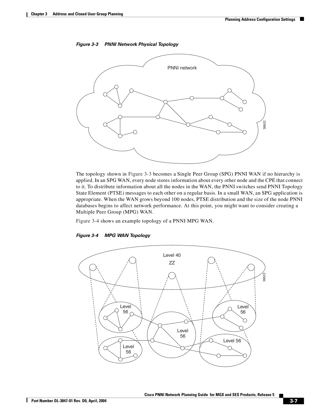
Figure 3-3 PNNI Network Physical Topology

PNNI network

38622

The topology shown in Figure 3-3becomes a Single Peer Group (SPG) PNNI WAN if no hierarchy is applied. In an SPG WAN, every node stores information about every other node and the CPE that connect to it. To distribute information about all the nodes in the WAN, the PNNI switches send PNNI Topology State Element (PTSE) messages to each other on a regular basis. In a small WAN, an SPG application is appropriate. When the WAN grows beyond 100 nodes, PTSE distribution and the size of the node PNNI databases begins to affect network performance. At this point, you might want to consider creating a Multiple Peer Group (MPG) WAN.

Figure 3-4shows an example topology of a PNNI MPG WAN.

Figure 3-4 MPG WAN Topology

Level 40

ZZ

38623

Level

Level

56

56

Level

56

Level 56

Level

56


Cisco PNNI Network Planning Guide for MGX and SES Products, Release 5


Part Number OL-3847-01 Rev. D0, April, 2004


3-7


Page 57
Image 57
Cisco Systems Network Router manual 4 shows an example topology of a PNNI MPG WAN