Chapter 1 Introduction to PNNI
The Hierarchical PNNI Network Topology
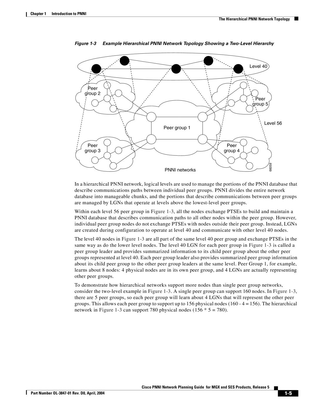
Figure 1-3 Example Hierarchical PNNI Network Topology Showing a Two-Level Hierarchy
Peer
group 2
Peer group 1
Peer
group 3
PNNI networks
Level 40
Ppeer
group 5
Level 56
Peer  group 4
66059
In a hierarchical PNNI network, logical levels are used to manage the portions of the PNNI database that describe communications paths between individual peer groups. PNNI divides the entire network database into manageable chunks, and the portions that describe communications between peer groups are managed by LGNs that operate at levels above the lowest-level peer groups.
Within each level 56 peer group in Figure 1-3, all the nodes exchange PTSEs to build and maintain a PNNI database that describes communication paths to all other nodes within the peer group. However, individual peer group nodes do not exchange PTSEs with nodes outside their peer group. Instead, LGNs are created during configuration to operate at level 40 and communicate with other level 40 nodes.
The level 40 nodes in Figure 1-3are all part of the same level 40 peer group and exchange PTSEs in the same way as do the lower level nodes. The level 40 LGN for each peer group in Figure 1-3is called a peer group leader and provides summarized information to its child peer group about the other peer groups represented at level 40. Each peer group leader also provides summarized peer group information about its child peer group to the other peer group leaders at the same level. Peer Group 1, for example, learns about 8 nodes: 4 physical nodes are in its own peer group, and 4 LGNs are actually representing other peer groups.
To demonstrate how hierarchical networks support more nodes than single peer group networks, consider the two-level example in Figure 1-3. A single peer group can support 160 nodes. In Figure 1-3, there are 5 peer groups, so each peer group will learn about 4 LGNs that will represent the other peer groups. This allows each peer group to support up to 156 physical nodes (160 - 4 = 156). The hierarchical network in Figure 1-3can support 780 physical nodes (156 * 5 = 780).
| | Cisco PNNI Network Planning Guide for MGX and SES Products, Release 5 | | |
| | |
| Part Number OL-3847-01 Rev. D0, April, 2004 | | | 1-5 | |
| | | |