bernard# show atm ilmi−status
Interface : ATM2/0/0 Interface Type : Private UNI (User−side)
ILMI VCC : (0, 16) ILMI Keepalive : Disabled |
| ||
ILMI State: | UpAndNormal |
|
|
Peer IP Addr: | 10.200.10.12 | Peer IF Name: | ATM0/0/0 |
Peer MaxVPIbits: | 8 | Peer MaxVCIbits: | 14 |
Active Prefix(s) : |
|
|
|
47.0091.8100.0000.0060.3e5a.4501
Casimir# show atm ilmi−status atm 0/0/0
Interface : ATM0/0/0 Interface Type : Private UNI (Network−side)
ILMI VCC : (0, 16) ILMI Keepalive : Enabled (5 Sec 4 Retries)
ILMI State: | UpAndNormal |
|
|
Peer IP Addr: | 15.1.1.1 | Peer IF Name: | ATM2/0/0 |
Peer MaxVPIbits: | 8 | Peer MaxVCIbits: | 16 |
Configured Prefix(s) : 47.0091.8100.0000.0060.3e5a.4501
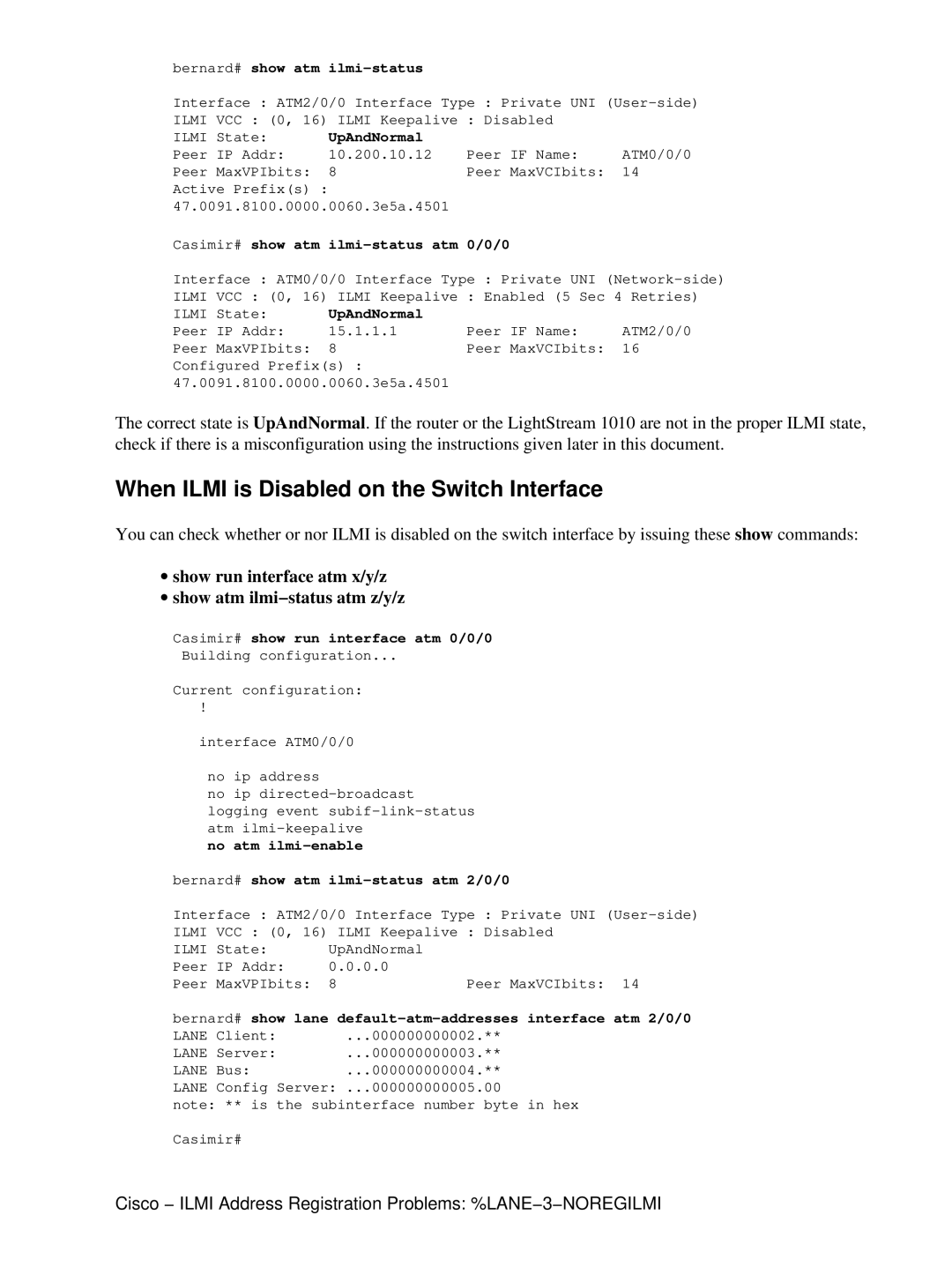
The correct state is UpAndNormal. If the router or the LightStream 1010 are not in the proper ILMI state, check if there is a misconfiguration using the instructions given later in this document.
When ILMI is Disabled on the Switch Interface
You can check whether or nor ILMI is disabled on the switch interface by issuing these show commands:
∙show run interface atm x/y/z
∙show atm ilmi−status atm z/y/z
Casimir# show run interface atm 0/0/0
Building configuration...
Current configuration:
!
interface ATM0/0/0
no ip address
no ip directed−broadcast logging event subif−link−status atm ilmi−keepalive
no atm ilmi−enable
bernard# show atm ilmi−status atm 2/0/0
Interface : ATM2/0/0 Interface Type : Private UNI (User−side)
ILMI VCC : (0, 16) ILMI Keepalive : Disabled
ILMI State: | UpAndNormal |
|
Peer IP Addr: | 0.0.0.0 |
|
Peer MaxVPIbits: | 8 | Peer MaxVCIbits: 14 |
bernard# show lane default−atm−addresses interface atm 2/0/0
LANE Client: | ...000000000002.** |
LANE Server: | ...000000000003.** |
LANE Bus: | ...000000000004.** |
LANE Config Server: ...000000000005.00
note: ** is the subinterface number byte in hex
Casimir#
Cisco − ILMI Address Registration Problems: %LANE−3−NOREGILMI
