Chapter 2 Camera Installation
IP Camera Installation
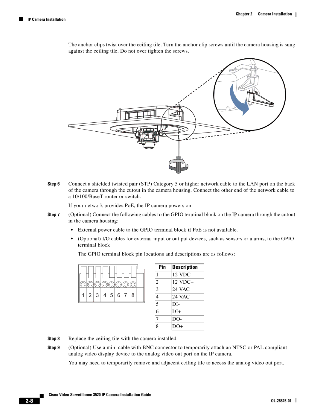
The anchor clips twist over the ceiling tile. Turn the anchor clip screws until the camera housing is snug against the ceiling tile. Do not over tighten the screws.
Step 6 Connect a shielded twisted pair (STP) Category 5 or higher network cable to the LAN port on the back of the camera through the cutout in the camera housing. Connect the other end of the network cable to a 10/100/BaseT router or switch.
If your network provides PoE, the IP camera powers on.
Step 7 (Optional) Connect the following cables to the GPIO terminal block on the IP camera through the cutout in the camera housing:
•External power cable to the GPIO terminal block if PoE is not available.
•(Optional) I/O cables for external input or out put devices, such as sensors or alarms, to the GPIO terminal block
The GPIO terminal block pin locations and descriptions are as follows:
1 2 3 4 5 6 7 8
Pin | Description |
|
|
1 | 12 VDC- |
|
|
2 | 12 VDC+ |
|
|
3 | 24 VAC |
|
|
4 | 24 VAC |
|
|
5 | DI- |
|
|
6 | DI+ |
|
|
7 | DO- |
|
|
8 | DO+ |
|
|
Step 8 Replace the ceiling tile with the camera installed.
Step 9 (Optional) Use a mini cable with BNC connector to temporarily attach an NTSC or PAL compliant analog video display device to the analog video out port on the IP camera.
You may need to temporarily remove and adjacent ceiling tile to access the analog video out port.
Cisco Video Surveillance 3520 IP Camera Installation Guide
|
| |
|