Chapter 6 Adding Cisco IOS Routers to Cisco WAPMS
Configuring ATM and Frame Relay Circuits
Configuring ATM and Frame Relay Circuits
You configure Frame Relay or ATM virtual circuits for the router in the Circuits pane of the Network Configuration window (see Figure
Configuring circuits involves:
•adding the circuit end points to the access lines
•customizing the circuit end points (optional)
•configuring the circuit connections between the circuit end points.
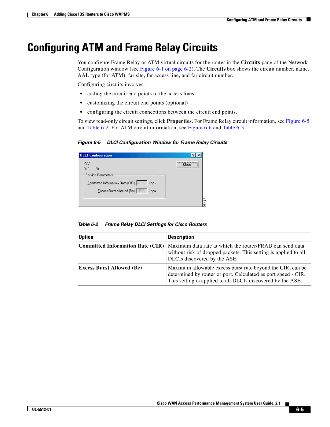
To view
Figure 6-5 DLCI Configuration Window for Frame Relay Circuits
Table 6-2 Frame Relay DLCI Settings for Cisco Routers
Option | Description |
|
|
Committed Information Rate (CIR) | Maximum data rate at which the router/FRAD can send data |
| without risk of dropped packets. This setting is applied to all |
| DLCIs discovered by the ASE. |
|
|
Excess Burst Allowed (Be) | Maximum allowable excess burst rate beyond the CIR; can be |
| determined by router or port. Calculated as port speed - CIR. |
| This setting is applied to all DLCIs discovered by the ASE. |
|
|
Cisco WAN Access Performance Management System User Guide, 2.1
|
| ||
|
|
