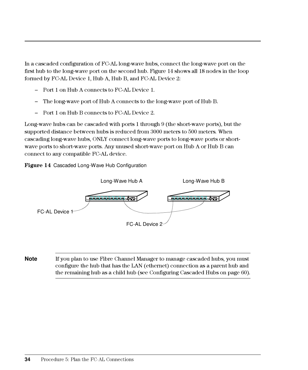
In a cascaded configuration of FC-AL long-wave hubs, connect the long-wave port on the first hub to the long-wave port on the second hub. Figure 14 shows all 18 nodes in the loop formed by FC-AL Device 1, Hub A, Hub B, and FC-AL Device 2:
–Port 1 on Hub A connects to FC-AL Device 1.
–The long-wave port of Hub A connects to the long-wave port of Hub B.
–Port 1 on Hub B connects to FC-AL Device 2.
Long-wave hubs can be cascaded with ports 1 through 9 (the short-wave ports), but the supported distance between hubs is reduced from 3000 meters to 500 meters. When cascading long-wave hubs, ONLY connect long-wave ports to long-wave ports or short- wave ports to short-wave ports. Any unused short-wave port on Hub A or Hub B can connect to any compatible FC-AL device.
Figure 14 Cascaded Long-Wave Hub Configuration | |
Long-Wave Hub A | Long-Wave Hub B |
FC-AL Device 1
FC-AL Device 2 
Note If you plan to use Fibre Channel Manager to manage cascaded hubs, you must configure the hub that has the LAN (ethernet) connection as a parent hub and the remaining hub as a child hub (see Configuring Cascaded Hubs on page 60).
34Procedure 5: Plan the FC-AL Connections

![]()
![]()
![]()
![]()
![]()
![]()
![]()
![]()
![]()
![]()
![]()
![]()
![]()
![]()
![]()
![]()
![]()
![]()
![]()
![]()
![]()
