Communications Interface
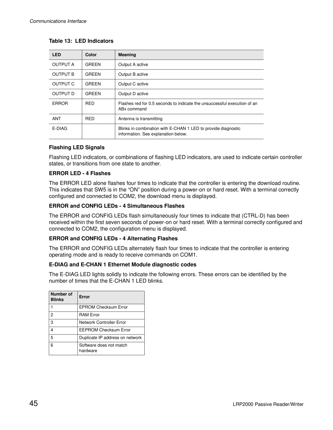
Table 13: LED Indicators
LED | Color | Meaning |
|
|
|
OUTPUT A | GREEN | Output A active |
|
|
|
OUTPUT B | GREEN | Output B active |
|
|
|
OUTPUT C | GREEN | Output C active |
|
|
|
OUTPUT D | GREEN | Output D active |
|
|
|
ERROR | RED | Flashes red for 0.5 seconds to indicate the unsuccessful execution of an |
|
| ABx command |
|
|
|
ANT | RED | Antenna is transmitting |
|
|
|
|
| Blinks in combination with |
|
| information. See explanation below. |
|
|
|
Flashing LED Signals
Flashing LED indicators, or combinations of flashing LED indicators, are used to indicate certain controller states, or transitions from one state to another.
ERROR LED - 4 Flashes
The ERROR LED alone flashes four times to indicate that the controller is entering the download routine. This indicates that SW5 is in the “ON” position during a
ERROR and CONFIG LEDs - 4 Simultaneous Flashes
The ERROR and CONFIG LEDs flash simultaneously four times to indicate that
ERROR and CONFIG LEDs - 4 Alternating Flashes
The ERROR and CONFIG LEDs alternately flash four times to indicate that the controller is entering operating mode and is ready to receive commands on COM1.
E-DIAG and E-CHAN 1 Ethernet Module diagnostic codes
The
Number of | Error | |
Blinks | ||
| ||
|
|
1EPROM Checksum Error
2RAM Error
3Network Controller Error
4EEPROM Checksum Error
5Duplicate IP address on network
6Software does not match hardware
45 | LRP2000 Passive Reader/Writer |