Communications Interface
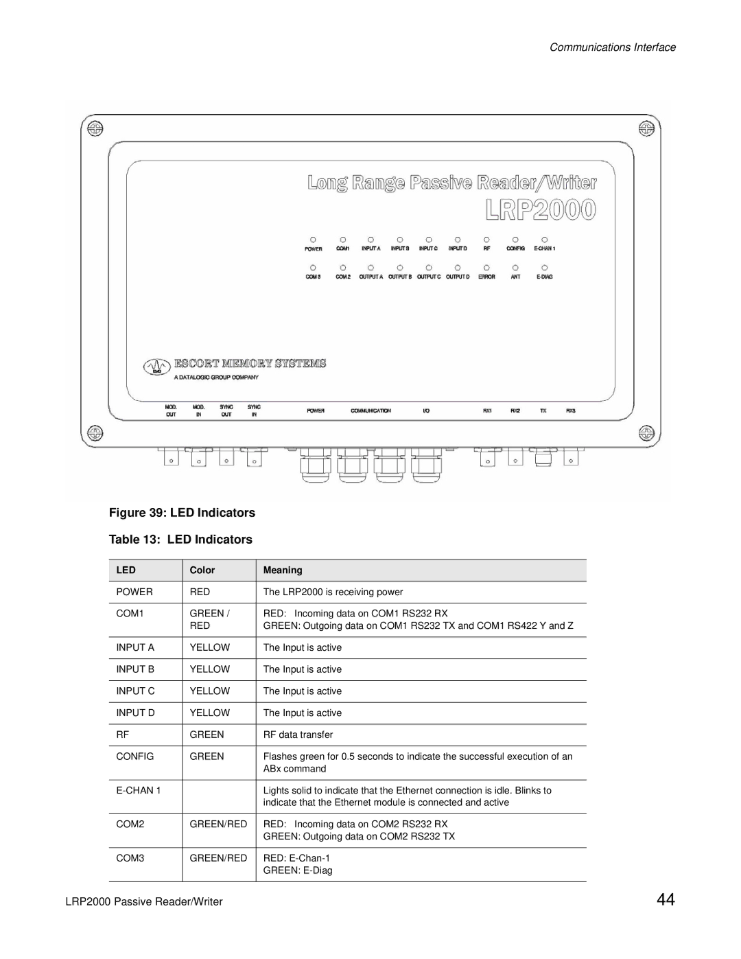
Figure 39: LED Indicators
Table 13: LED Indicators
LED | Color | Meaning |
|
|
|
POWER | RED | The LRP2000 is receiving power |
|
|
|
COM1 | GREEN / | RED: Incoming data on COM1 RS232 RX |
| RED | GREEN: Outgoing data on COM1 RS232 TX and COM1 RS422 Y and Z |
|
|
|
INPUT A | YELLOW | The Input is active |
|
|
|
INPUT B | YELLOW | The Input is active |
|
|
|
INPUT C | YELLOW | The Input is active |
|
|
|
INPUT D | YELLOW | The Input is active |
|
|
|
RF | GREEN | RF data transfer |
|
|
|
CONFIG | GREEN | Flashes green for 0.5 seconds to indicate the successful execution of an |
|
| ABx command |
|
|
|
|
| Lights solid to indicate that the Ethernet connection is idle. Blinks to |
|
| indicate that the Ethernet module is connected and active |
|
|
|
COM2 | GREEN/RED | RED: Incoming data on COM2 RS232 RX |
|
| GREEN: Outgoing data on COM2 RS232 TX |
|
|
|
COM3 | GREEN/RED | RED: |
|
| GREEN: |
|
|
|
LRP2000 Passive Reader/Writer | 44 |
