Electrical Interface
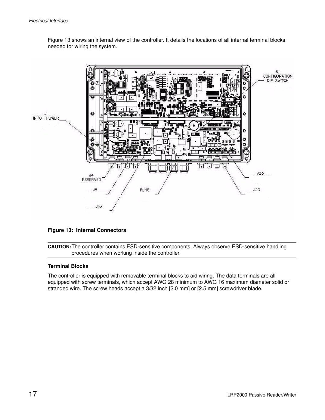
Figure 13 shows an internal view of the controller. It details the locations of all internal terminal blocks needed for wiring the system.
Figure 13: Internal Connectors
CAUTION:The controller contains
Terminal Blocks
The controller is equipped with removable terminal blocks to aid wiring. The data terminals are all equipped with screw terminals, which accept AWG 28 minimum to AWG 16 maximum diameter solid or stranded wire. The screw heads accept a 3/32 inch [2.0 mm] or [2.5 mm] screwdriver blade.
17 | LRP2000 Passive Reader/Writer |