Electrical Interface
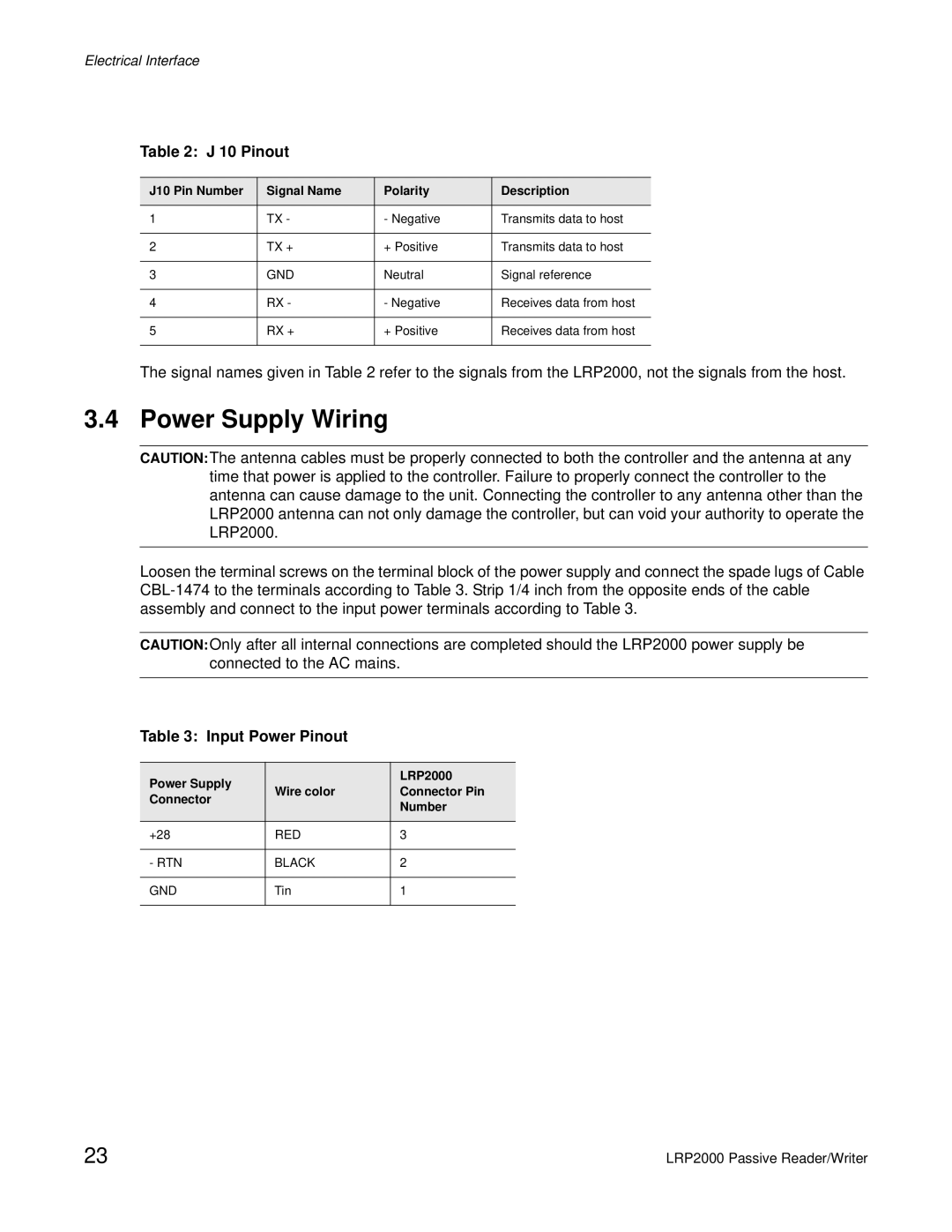
Table 2: J 10 Pinout
J10 Pin Number | Signal Name | Polarity | Description |
|
|
|
|
1 | TX - | - Negative | Transmits data to host |
|
|
|
|
2 | TX + | + Positive | Transmits data to host |
|
|
|
|
3 | GND | Neutral | Signal reference |
|
|
|
|
4 | RX - | - Negative | Receives data from host |
|
|
|
|
5 | RX + | + Positive | Receives data from host |
|
|
|
|
The signal names given in Table 2 refer to the signals from the LRP2000, not the signals from the host.
3.4 Power Supply Wiring
CAUTION:The antenna cables must be properly connected to both the controller and the antenna at any time that power is applied to the controller. Failure to properly connect the controller to the antenna can cause damage to the unit. Connecting the controller to any antenna other than the LRP2000 antenna can not only damage the controller, but can void your authority to operate the LRP2000.
Loosen the terminal screws on the terminal block of the power supply and connect the spade lugs of Cable
CAUTION:Only after all internal connections are completed should the LRP2000 power supply be connected to the AC mains.
Table 3: Input Power Pinout
Power Supply |
| LRP2000 | |
Wire color | Connector Pin | ||
Connector | |||
| Number | ||
|
| ||
|
|
| |
+28 | RED | 3 | |
|
|
| |
- RTN | BLACK | 2 | |
|
|
| |
GND | Tin | 1 | |
|
|
|
23 | LRP2000 Passive Reader/Writer |