Manuals
/
Escort
/
Computer Equipment
/
Switch
Escort
LRP2000
manual
FCC Certifications
Models:
LRP2000
1
8
140
140
Download
140 pages
32.66 Kb
5
6
7
8
9
10
11
12
Specifications
Install
Error codes
Flashing LED Signals
COM1 Defaults
LED Indicators
Connectors and Wiring
Warranty
Dimension
Master/Slave Configuration
Page 8
Image 8
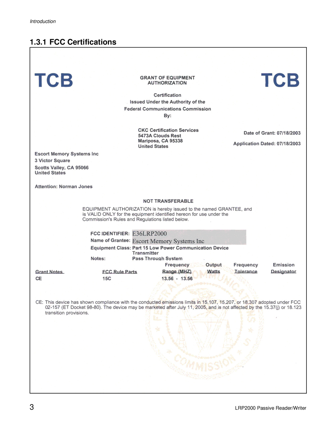
Introduction
1.3.1 FCC Certifications
3
LRP2000 Passive Reader/Writer
Page 7
Page 9
Page 8
Image 8
Page 7
Page 9
Contents
LRP2000 Passive Reader/Writer
Escort Memory Systems Warranty
Table of Contents
Rfid Communications
Iii
Introduction
Unpacking and Inspection
FCC Compliance
FCC Certifications
Introduction
CE Statement
CE Certification
Changes and Modifications
Dimensions
LRP2000 Dimensions
LRP2000 Mounting Hole Locations and Dimensions
LRP2000-23 Antenna Dimensions
LRP2000-26 Antenna Dimensions
Installation
1 LRP2000-26 Antenna Assembly
Installing the Antenna
Antenna Environment
Green Orientation Dots Location
Connectors Joining Plate
Green Dots Joining Plate
Joining Plate and Fasteners
Completed LRP2000-26 Antenna
Connectors and Wiring
RF Connectors and Strain Relief
Internal Connectors Terminal Blocks
Antenna Connectors
Antenna Cabling
Connecting Single Antenna System
Single Antenna System Connections
Connecting a Dual Antenna System
Dual Antenna System Connections
RS232 Pinouts, J8 Terminal Block
J8 Pin Number Interface J8 Signal Name DB9 Pin DB25 Pin
Data Terminal Blocks
J10 COM1 RS422
Power Supply Wiring
Input Power Pinout
J10 Pin Number Signal Name Polarity Description
Power Supply LRP2000 Wire color Connector Pin Number
Input Power Supply Lugs
RS232 Wiring RS422 Wiring and Termination
Ethernet Wiring
Digital I/O Circuitry
Connector Pin Signal Name Polarity Number
Inputs
Outputs
Terminal Signal Name Polarity Number
Input from Sourcing Contact
Input from NPN Sensor
Sourcing Output Contact
Sinking Output LED Driver
J32 J34
Master/Slave Configuration
Setting Jumper 32 on the Master
DIP Switch Settings on the Slave
Master DIP Switch Settings
Bank Position
OFF
Setting Jumper J16 on the Slave
Slave DIP Switch Settings
Configuring the Serial Interface
COM1 Defaults
1 COM1
2 COM2
Baud Rate 1200, 2400 9600, 19200 bps
COM2 Defaults
COM2 Parameters
Digital Board DIP Switch
Dip Switch Settings
Download Baud Rate Interface Restore Defaults
Settings
Configuring the Ethernet Module for Network Communication
Default IP Address
Optional Ethernet Interface
Ignored
Menu Loading
Configuration
LED Indicators
Server Properties
Color Meaning
Flashing LED Signals
Error LED 4 Flashes
Error and Config LEDs 4 Simultaneous Flashes
Error and Config LEDs 4 Alternating Flashes
Faulty Network Connection No Dhcp Response Received
How to Enter the Menu Configuration
LRP2000 Standard PC Serial Port
Set COM2 Parameters
Set-Up Operating Parameters
Set COM1 Parameters
Framing Editing
Set Operating Mode
Operating Mode
Checksum? 0 Disabled 1 Enabled
Power up in Continuous Read Mode?
Delay Between Identical Decodes
Start Address
Length
Return to Main Menu
Restore Factory Defaults
Set RF Communication
Download New Program
Downloading DSP Firmware
Exit to Operating Mode
Command protocols
Conventions
ABx Command Set Listings
Single Tag Commands
Multi-tag Commands
User I/O Commands
Command Parameters
Multi-tag Command Parameters
Start Continuous Read
Field Number Content Bytes
Standard ABx Protocol
Single Tag Example
Multi-tag Example
ABxS Command 04H Fill Tag
Command from Host
Example
Field Remarks
ABxS Command 05H Read
Response from Controller
ABxS Command 06H Write
E0H
ABxS Command 07H Read Tag Serial Number
ACH
ABxS Command 08H Tag Search
ABxS Command 0DH Stop/Start Continuous Read
Config Blink
Command Response Field Remarks
Behavior Description
ANT
Response from controller
ABxS Command 14H Get Memory Status
Field Content
Description
ABxS Command 16H Write Family Code
ABxS Command 17H Lock Family Code
ABxS Command 82H SN Read All
6CH
AAH FFH
0BH
ABxS Command 83H Start/Stop Continuous SN Read All
1EH
FCH
4BH
C5H
ABxS Command 84H Fill Tag All
Response to a successful command follows this form
ABxS Command 85H Read All
Termination Packet
ABxS Command 86H Write All
ABxS Command 87H Read Tag SN All
6EH
3CH
D2H
ABxS Command 88H Tag Search All
ABxS Command 8BH Write Family Code All
AAH 8BH
ABxS Command 8CH Lock Family Code All
AAH 8CH
ABxS Command 8DH Start/Stop Continuous Read All
AAH 8DH
Data response from controller
ABxS Command 91H Memory Lock All
Command is formatted as shown below
ABxS Command 94H SN Fill
00H 01H SN byte
F3H
ABxS Command 95H SN Read
ABH
ABxS Command 96H SN Write
A4H
ABxS Command 10H Set Output
Remarks LSB Bit Output D Output C Output B Output a
0CH
0EH
ABxS Command 11H Input Status
Remarks LSB Bit Input D Input C Input B Input a
Field Contents
ABx Fast Protocol
Packet Size
Checksum
ABx Fast Single Tag Command Structure
ABx Fast Multi-tag Command Structure
ABxF Command 04H Fill Tag
Header 0202H Command Size
ABxF Command 05H Read
Command from Host Field Content
Response from Controller Field Content
AEH
ABxF Command 06H Write
E7H
F8H
ABxF Command 07H Read Tag Serial Number
EEH
A3H
ABxF Command 08H Tag Search
F2H
F6H
ABxF Command 0DH Start/Stop Continuous Read
1DH
F1H
ABxF Command 14H Get Memory Status
E1H
E8H
ABxF Command 16H Write Family Code
E5H
ABxF Command 17H Lock Family Code
ABxF Command 82H Read Data and SN All
101
A6H
Command from Host Response from Controller Field Content
6FH
ABxF Command 83H Start/Stop Continuous SN Read All
103
6AH
7BH
105
ABxF Command 84H Fill All
106
ABxF Command 85H Block Read All
107
EBH
C8H
ABxF Command 86H Block Write All
109
ABxF Command 87H Read Tag SN All
110
9BH
F4H
ABxF Command 88H Tag Search All
ETX
ABxF Command 8DH Stop/Start Continuous Read All
113
ABxF Command 91H Memory Lock All
114
ABxF Command 8BH Write Family Code All
115
ABxF Command 8CH Lock Family Code All
F7H
117
ABxF Command 94H SN Fill
Response form Controller Field Content
B0H
9DH
ABxF Command 95H SN Block Read
119
120
ABxF Command 96H SN Block Write
121
4DH
ABxF Command 10H Set Output
123
Output LSB Bit Status
Output D Output C Output B Output a Byte
ABxF Command 11H Input Status
124
EAH
125
EDH
ABx Ascii Protocol Command Structure
Command Packet Structure
ABx Ascii Protocol
ABx Ascii Protocol Response Structure
127
Command/Response Size
Example Ascii Command, Fill Tag
Response from Controller Field Ascii Hex Ascii String Value
Command from Host Field Ascii Hex Ascii String Value
STX
ABx Error Codes
Multi-tag Error Codes
ABx Standard Error Codes
Error Code Description
ABx Fast Error Codes
ABx Ascii Error Codes
Field Bytes Contents
Field Number of Ascii Contents Characters
Multi-tag Command Error Code
131
Mechanical Specifications
Electrical
Communication
Environmental
Accessories
Available Models
Options
Tags
134
Decimal Hex Character
135
DEL
Top
Page
Image
Contents