Electrical Interface
3.2 Antenna Cabling
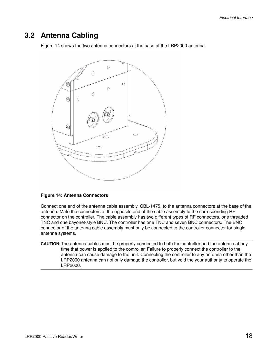
Figure 14 shows the two antenna connectors at the base of the LRP2000 antenna.
Figure 14: Antenna Connectors
Connect one end of the antenna cable assembly,
CAUTION:The antenna cables must be properly connected to both the controller and the antenna at any time that power is applied to the controller. Failure to properly connect the controller to the antenna can cause damage to the unit. Connecting the controller to any antenna other than the LRP2000 antenna can not only damage the controller, but void the your authority to operate the LRP2000.
LRP2000 Passive Reader/Writer | 18 |