Electrical Interface
3.3 Data Terminal Blocks
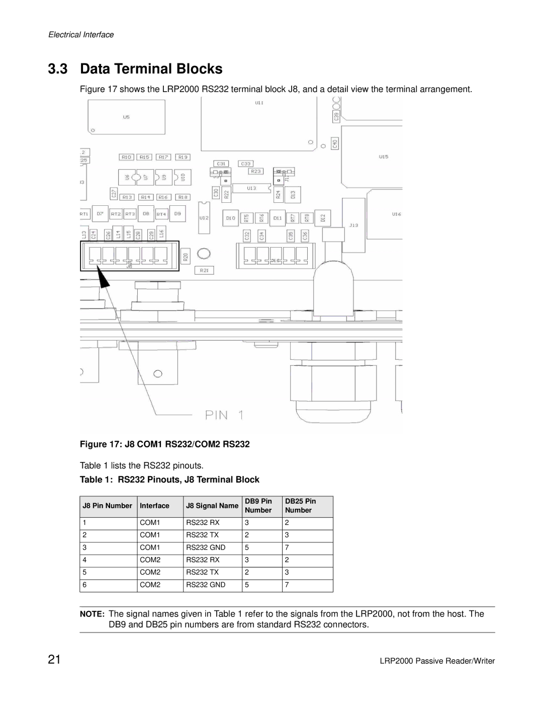
Figure 17 shows the LRP2000 RS232 terminal block J8, and a detail view the terminal arrangement.
Figure 17: J8 COM1 RS232/COM2 RS232
Table 1 lists the RS232 pinouts.
Table 1: RS232 Pinouts, J8 Terminal Block
J8 Pin Number | Interface | J8 Signal Name | DB9 Pin | DB25 Pin |
Number | Number | |||
1 | COM1 | RS232 RX | 3 | 2 |
|
|
|
|
|
2 | COM1 | RS232 TX | 2 | 3 |
|
|
|
|
|
3 | COM1 | RS232 GND | 5 | 7 |
|
|
|
|
|
4 | COM2 | RS232 RX | 3 | 2 |
|
|
|
|
|
5 | COM2 | RS232 TX | 2 | 3 |
|
|
|
|
|
6 | COM2 | RS232 GND | 5 | 7 |
|
|
|
|
|
NOTE: The signal names given in Table 1 refer to the signals from the LRP2000, not from the host. The DB9 and DB25 pin numbers are from standard RS232 connectors.
21 | LRP2000 Passive Reader/Writer |