Communications Interface
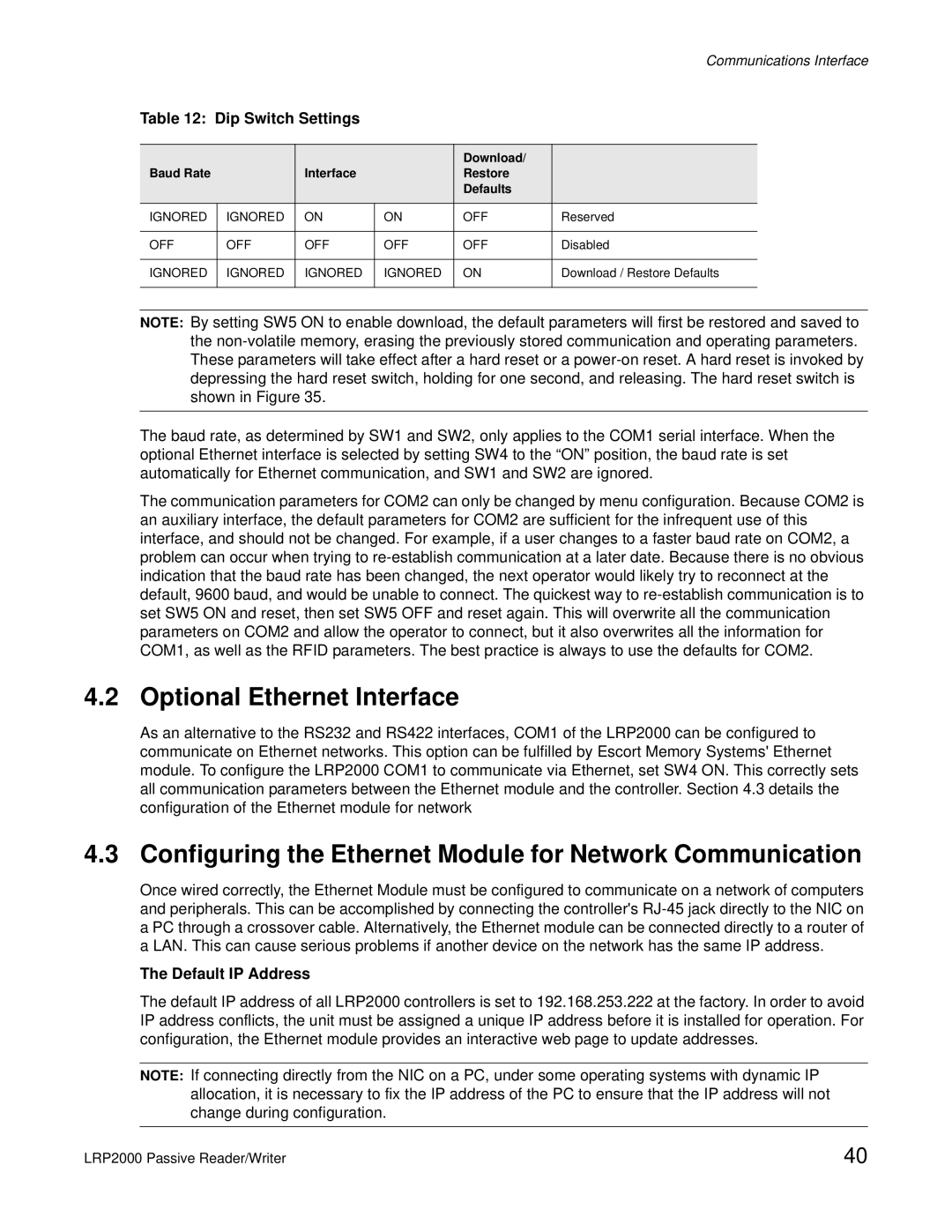
Table 12: Dip Switch Settings
|
|
|
| Download/ |
|
Baud Rate |
| Interface |
| Restore |
|
|
|
|
| Defaults |
|
IGNORED | IGNORED | ON | ON | OFF | Reserved |
|
|
|
|
|
|
OFF | OFF | OFF | OFF | OFF | Disabled |
|
|
|
|
|
|
IGNORED | IGNORED | IGNORED | IGNORED | ON | Download / Restore Defaults |
|
|
|
|
|
|
NOTE: By setting SW5 ON to enable download, the default parameters will first be restored and saved to the
The baud rate, as determined by SW1 and SW2, only applies to the COM1 serial interface. When the optional Ethernet interface is selected by setting SW4 to the “ON” position, the baud rate is set automatically for Ethernet communication, and SW1 and SW2 are ignored.
The communication parameters for COM2 can only be changed by menu configuration. Because COM2 is an auxiliary interface, the default parameters for COM2 are sufficient for the infrequent use of this interface, and should not be changed. For example, if a user changes to a faster baud rate on COM2, a problem can occur when trying to
4.2 Optional Ethernet Interface
As an alternative to the RS232 and RS422 interfaces, COM1 of the LRP2000 can be configured to communicate on Ethernet networks. This option can be fulfilled by Escort Memory Systems' Ethernet module. To configure the LRP2000 COM1 to communicate via Ethernet, set SW4 ON. This correctly sets all communication parameters between the Ethernet module and the controller. Section 4.3 details the configuration of the Ethernet module for network
4.3 Configuring the Ethernet Module for Network Communication
Once wired correctly, the Ethernet Module must be configured to communicate on a network of computers and peripherals. This can be accomplished by connecting the controller's
The Default IP Address
The default IP address of all LRP2000 controllers is set to 192.168.253.222 at the factory. In order to avoid IP address conflicts, the unit must be assigned a unique IP address before it is installed for operation. For configuration, the Ethernet module provides an interactive web page to update addresses.
NOTE: If connecting directly from the NIC on a PC, under some operating systems with dynamic IP allocation, it is necessary to fix the IP address of the PC to ensure that the IP address will not change during configuration.
LRP2000 Passive Reader/Writer | 40 |