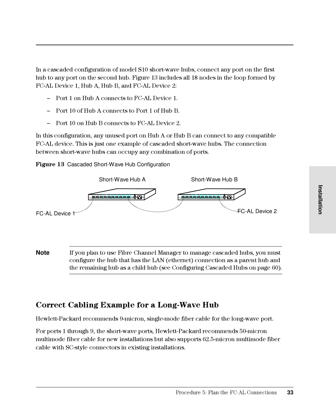
In a cascaded configuration of model S10 short-wave hubs, connect any port on the first hub to any port on the second hub. Figure 13 includes all 18 nodes in the loop formed by FC-AL Device 1, Hub A, Hub B, and FC-AL Device 2:

Port 1 on Hub A connects to FC-AL Device 1.

Port 10 of Hub A connects to Port 1 of Hub B.

Port 10 on Hub B connects to FC-AL Device 2.

In this configuration, any unused port on Hub A or Hub B can connect to any compatible FC-AL device. This is just one example of cascaded short-wave hubs. The connection between short-wave hubs can occupy any combination of ports.

Figure 13 Cascaded Short-Wave Hub Configuration

Short-Wave Hub A

Short-Wave Hub B

... ... ... ... ... ... ... ... ... ........

... ... ... ... ... ... ... ... ... ...

.....

FC-AL Device 1

FC-AL Device 2


Note If you plan to use Fibre Channel Manager to manage cascaded hubs, you must configure the hub that has the LAN (ethernet) connection as a parent hub and the remaining hub as a child hub (see Configuring Cascaded Hubs on page 60).

Correct Cabling Example for a Long-Wave Hub

Hewlett-Packard recommends 9-micron, single-mode fiber cable for the long-wave port.

For ports 1 through 9, the short-wave ports, Hewlett-Packard recommends 50-micron multimode fiber cable for new installations but also supports 62.5-micron multimode fiber cable with SC-style connectors in existing installations.

Installation

Procedure 5: Plan the FC-AL Connections 33