Chapter 3 Product Hardware
Modularity and Ancillary Equipment
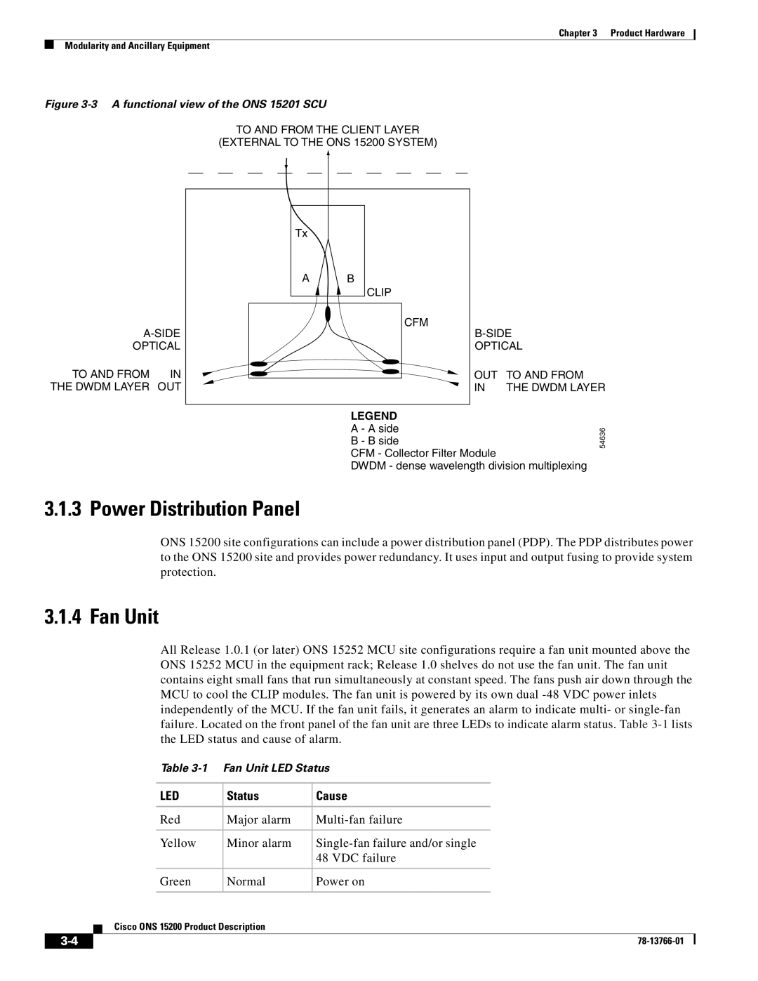
Figure 3-3 A functional view of the ONS 15201 SCU
TO AND FROM THE CLIENT LAYER
(EXTERNAL TO THE ONS 15200 SYSTEM)
OPTICAL
TO AND FROM | IN |
THE DWDM LAYER | OUT |
Tx |
|
|
A | B |
|
| CLIP |
|
| CFM |
|
| ||
| OPTICAL | |
| OUT | TO AND FROM |
| IN | THE DWDM LAYER |
LEGEND |
| |
A - A side | 54636 | |
B - B side | ||
|
CFM - Collector Filter Module
DWDM - dense wavelength division multiplexing
3.1.3 Power Distribution Panel
ONS 15200 site configurations can include a power distribution panel (PDP). The PDP distributes power to the ONS 15200 site and provides power redundancy. It uses input and output fusing to provide system protection.
3.1.4 Fan Unit
All Release 1.0.1 (or later) ONS 15252 MCU site configurations require a fan unit mounted above the ONS 15252 MCU in the equipment rack; Release 1.0 shelves do not use the fan unit. The fan unit contains eight small fans that run simultaneously at constant speed. The fans push air down through the MCU to cool the CLIP modules. The fan unit is powered by its own dual
Table
|
|
| LED | Status | Cause | |
|
|
| Red | Major alarm | ||
|
|
| Yellow | Minor alarm | ||
|
|
|
|
| 48 VDC failure | |
|
|
| Green | Normal | Power on | |
|
|
| Cisco ONS 15200 Product Description |
|
| |
|
|
|
|
| ||
|
|
|
|
| ||
|
|
|
|
| ||