Chapter 3 Product Hardware
Power and Grounding
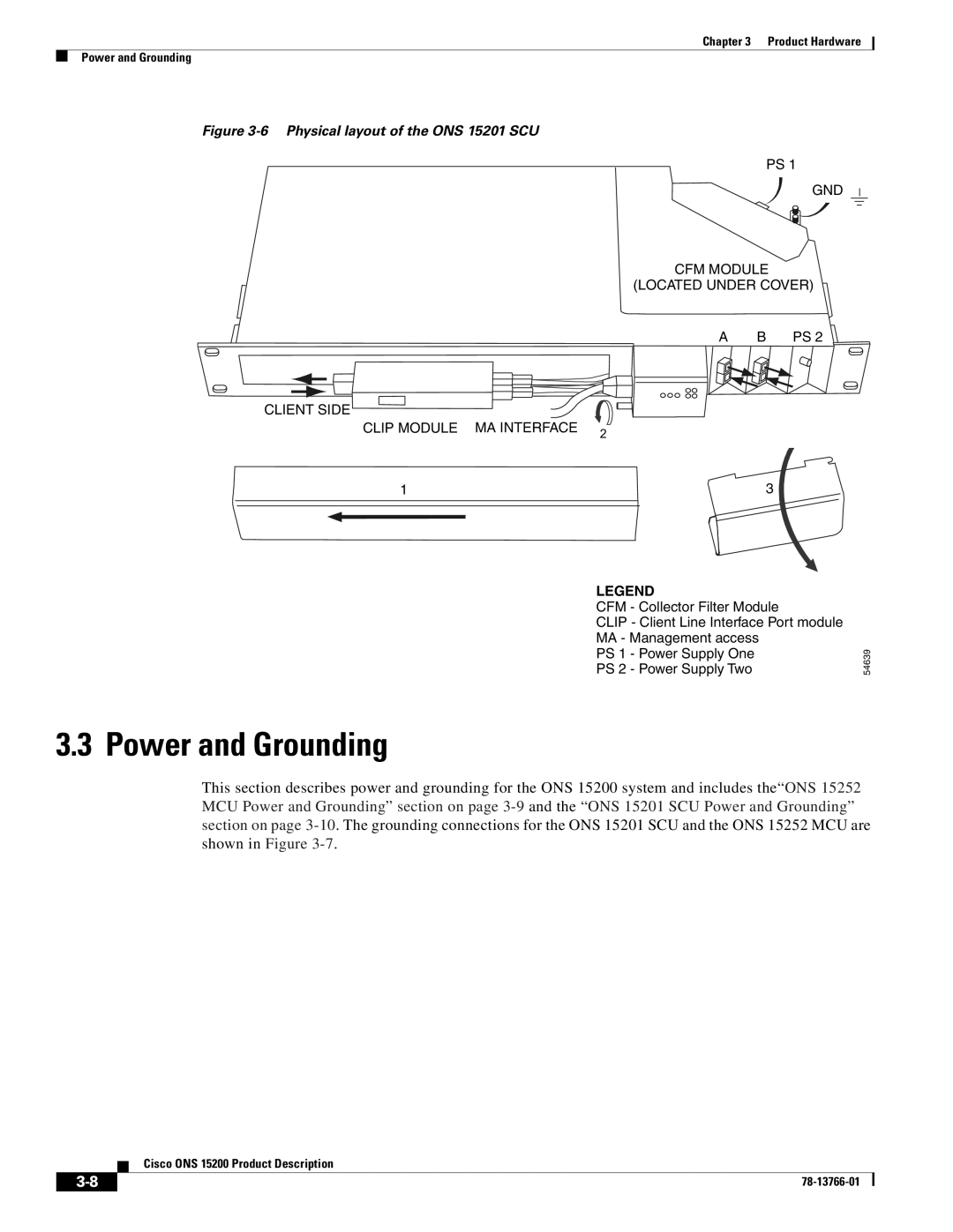
Figure 3-6 Physical layout of the ONS 15201 SCU
PS 1
GND
CFM MODULE
(LOCATED UNDER COVER)
A | B PS 2 |
CLIENT SIDE
CLIP MODULE | MA INTERFACE | 2 |
|
| |
1 |
| 3 |
LEGEND
CFM - Collector Filter Module
CLIP - Client Line Interface Port module MA - Management access
PS 1 - Power Supply One
PS 2 - Power Supply Two
54639
3.3 Power and Grounding
This section describes power and grounding for the ONS 15200 system and includes the“ONS 15252 MCU Power and Grounding” section on page
Cisco ONS 15200 Product Description
| ||
|