RPS 675 specifications
The Cisco Systems RPS 675, or Redundant Power System 675, is a high-performance power supply solution designed to enhance the reliability and availability of network equipment in critical data center environments. This redundant power system supports the continuous operation of Cisco switches, routers, and other devices, ensuring that organizations can maintain their network uptime even in the event of a power failure or disruption.One of the standout features of the RPS 675 is its ability to provide backup power to multiple Cisco devices. It can be connected to up to six compatible devices simultaneously, offering flexibility and scalability for various network architectures. This centralized power management not only reduces the need for multiple power sources but also simplifies the deployment of backup power solutions across the network.
In terms of technology, the RPS 675 incorporates advanced power management capabilities. It features an intelligent power distribution system, which optimally allocates power based on the requirements of connected devices. This ensures that critical devices receive the necessary power without overloading the system, enhancing overall energy efficiency. The system supports a wide range of input voltage options, making it suitable for various environments worldwide.
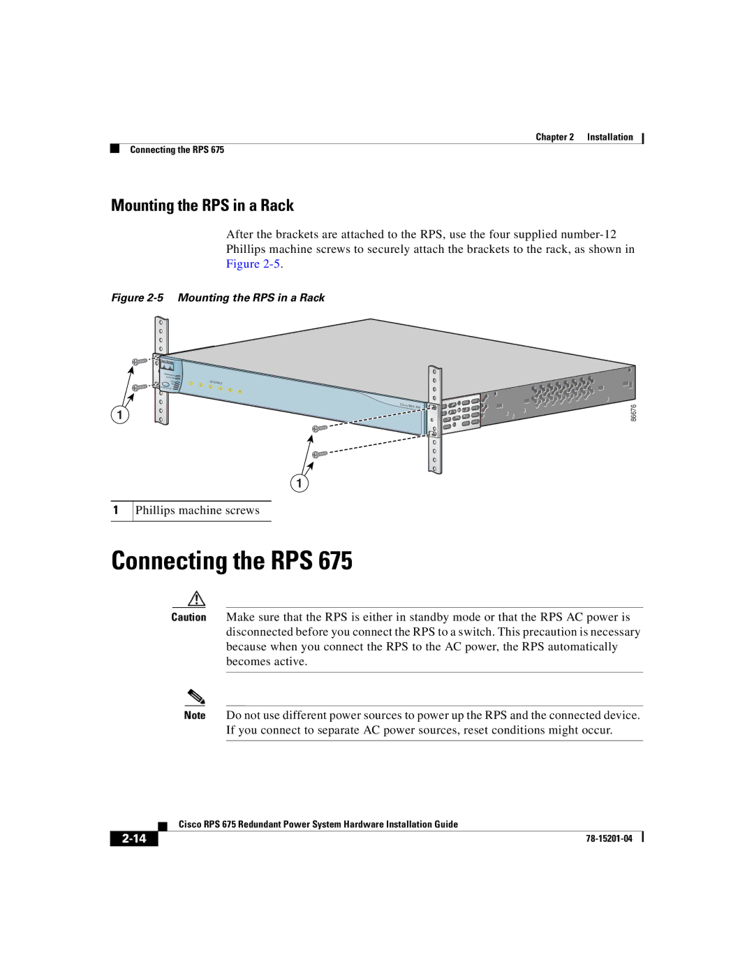
Another key characteristic of the RPS 675 is its compact design. The unit is engineered to fit into standard 19-inch racks, making it suitable for installation in both small and large data center environments. Its modular design allows for easy expansion and maintenance, ensuring that organizations can adapt their power needs as they grow.
The RPS 675 also boasts robust monitoring and management features. It includes an integrated web interface that provides real-time visibility into the power status of connected devices, as well as alerts for any potential issues. This proactive monitoring capability allows IT administrators to quickly identify and address power-related problems before they lead to network outages.
Overall, the Cisco Systems RPS 675 is an essential component for organizations requiring reliable and efficient power solutions for their networking equipment. With its multiple-device support, intelligent power management, compact design, and robust monitoring features, it stands out as a strategic investment for enhancing network resilience and operational continuity in today’s increasingly digital landscape.

