CBM-820 specifications
The Citizen Systems CBM-820 is a compact and versatile thermal printer designed to meet the varied needs of modern businesses, especially in retail and hospitality environments. Known for its reliability and performance, this printer is well-suited for high-volume printing tasks, making it an ideal choice for point-of-sale applications.One of the standout features of the CBM-820 is its fast printing speed, capable of producing receipts at an impressive rate of up to 200 mm per second. This speed ensures that businesses can efficiently process transactions, reducing customer wait times and enhancing the overall service experience. The printer supports various paper widths, providing flexibility to accommodate different receipt sizes and formats.
The CBM-820 utilizes advanced thermal printing technology, which eliminates the need for ink or toner, resulting in lower operating costs. The thermal print head has a long lifespan, ensuring durability and minimal maintenance requirements. Additionally, the printer supports multiple printing resolutions, delivering high-quality output that enhances the readability of printed text and graphics.
Connectivity is another strong point of the CBM-820. It offers various interface options, including USB, Ethernet, and serial connections, allowing seamless integration with existing point-of-sale systems. The printer is compatible with various operating systems, ensuring broad applicability for businesses using different software platforms.
Furthermore, the CBM-820 is designed with user convenience in mind. It features an easy-to-load paper mechanism that simplifies changing rolls, minimizing downtime during busy periods. The compact design of the printer allows it to fit neatly into limited counter spaces, making it a practical choice for retail and restaurant settings.
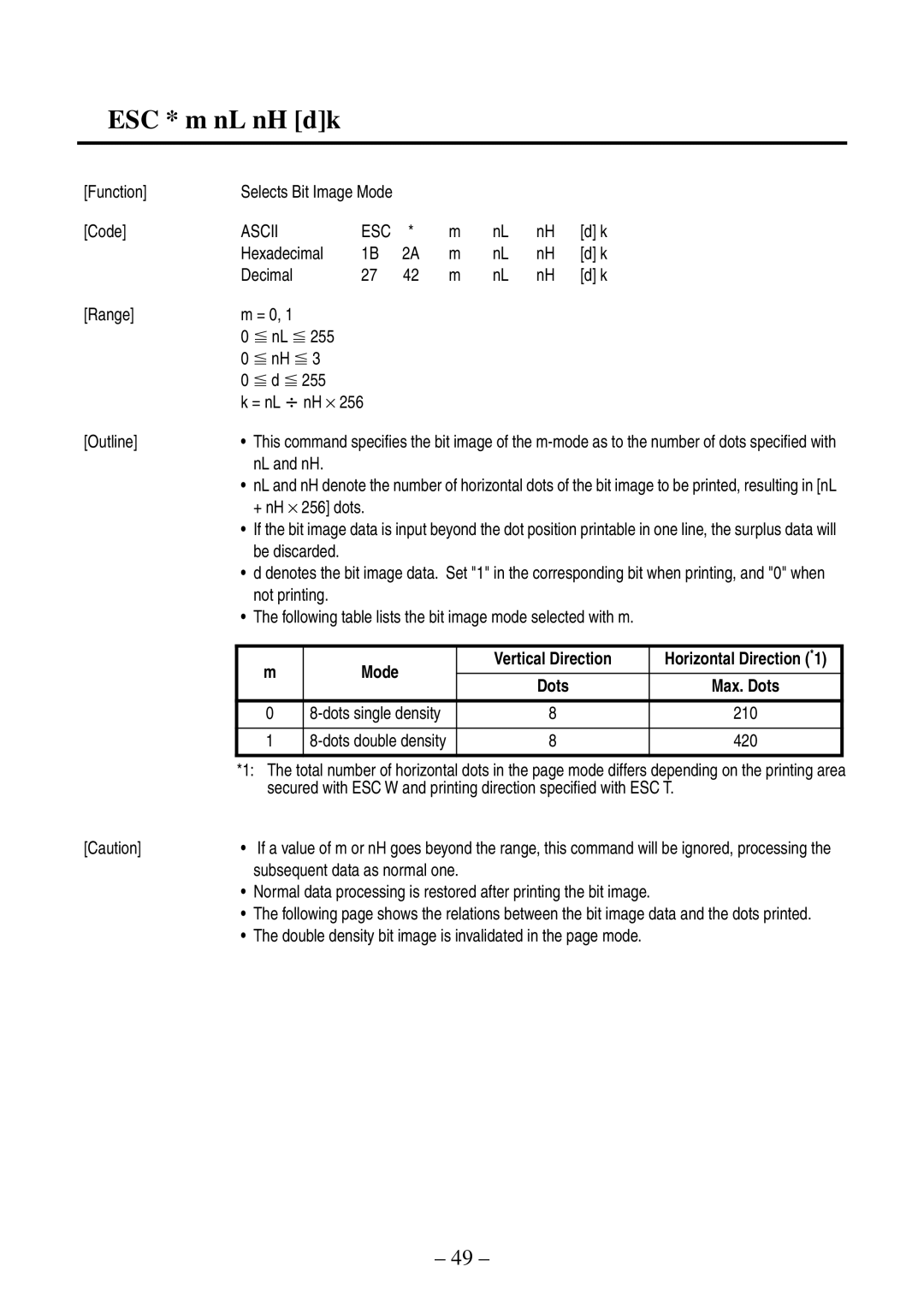
From a software perspective, the CBM-820 supports standardized command languages like ESC/POS, enabling easy integration into various applications. This adaptability makes it suitable for a wide range of industries, from traditional retail stores to mobile food vendors.
In terms of environmental considerations, Citizen Systems has designed the CBM-820 to be energy-efficient, consuming less power than many traditional printers. This not only helps businesses reduce their operating costs but also aligns with sustainable practices.
In conclusion, the Citizen Systems CBM-820 stands out as a high-performance thermal printer that combines speed, efficiency, and versatility. Its robust features and user-friendly design make it an excellent choice for any business looking to enhance their printing capabilities while maintaining cost-effectiveness.