2.3.4 Black Mark Layout and Operating Condition
J |
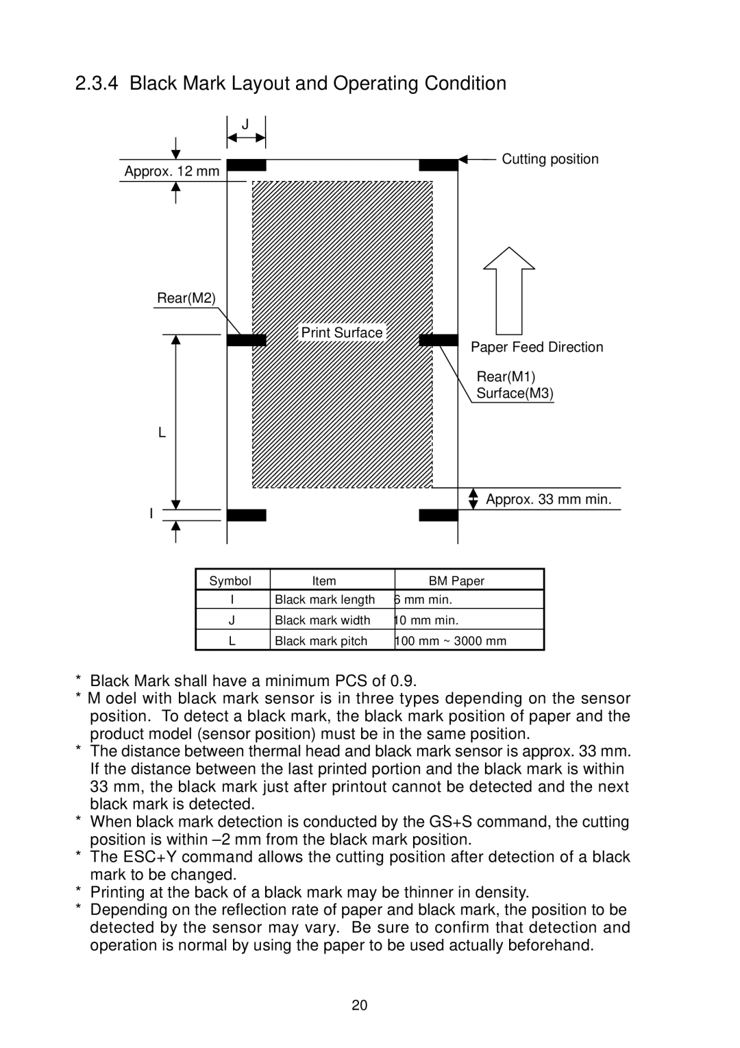
Cutting position |
Approx. 12 mm |
Rear(M2) |
Print Surface |
Paper Feed Direction |
Rear(M1) |
Surface(M3) |
L |
Approx. 33 mm min. |
I |
Symbol | Item | BM Paper |
I | Black mark length | 6 mm min. |
J | Black mark width | 10 mm min. |
L | Black mark pitch | 100 mm ~ 3000 mm |
*Black Mark shall have a minimum PCS of 0.9.
*Model with black mark sensor is in three types depending on the sensor position. To detect a black mark, the black mark position of paper and the product model (sensor position) must be in the same position.
*The distance between thermal head and black mark sensor is approx. 33 mm. If the distance between the last printed portion and the black mark is within 33 mm, the black mark just after printout cannot be detected and the next black mark is detected.
*When black mark detection is conducted by the GS+S command, the cutting position is within ±2 mm from the black mark position.
*The ESC+Y command allows the cutting position after detection of a black mark to be changed.
*Printing at the back of a black mark may be thinner in density.
*Depending on the reflection rate of paper and black mark, the position to be detected by the sensor may vary. Be sure to confirm that detection and operation is normal by using the paper to be used actually beforehand.
— 20 —