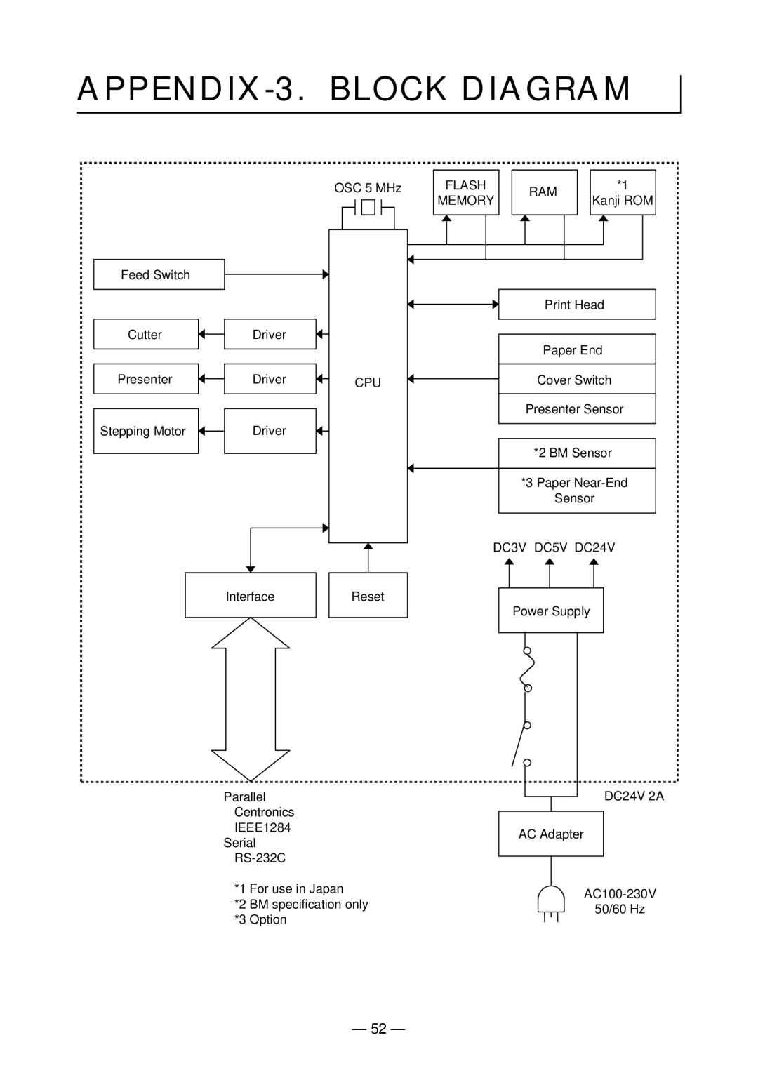
APPENDIX-3. BLOCK DIAGRAM
|
| OSC 5 MHz | FLASH | RAM | *1 |
|
|
| MEMORY |
| |
|
|
| Kanji ROM | ||
Feed Switch |
|
|
|
|
|
|
|
|
| Print Head |
|
Cutter | Driver |
|
|
|
|
|
|
|
| Paper End |
|
Presenter | Driver | CPU |
| Cover Switch |
|
|
|
|
| Presenter Sensor | |
Stepping Motor | Driver |
|
|
|
|
|
|
|
| *2 BM Sensor |
|
|
|
|
| *3 Paper | |
|
|
|
| Sensor |
|
|
|
| DC3V DC5V DC24V |
| |
| Interface | Reset |
|
|
|
|
|
|
| Power Supply |
|
| Parallel |
|
| DC24V 2A | |
| Centronics |
|
|
|
|
| IEEE1284 |
|
| AC Adapter |
|
| Serial |
|
|
| |
|
|
|
|
| |
|
|
|
|
| |
*1 | For use in Japan | ||
*2 | BM specification only | ||
50/60 Hz | |||
*3 | Option | ||
|
— 52 —
