4 | Controls and Connections |
Controls and Connections
Product overview
Front panel
AB C D E F
Figure 1. Front panel
A.RGB Out connects the
B.IR Receiver receives command signals from the IR remote control.
C.Video/RGB selects Video or RGB output.
D.NTSC/PAL Selects either NTSC or PAL video output, depending on the system used in your area.
E.Power turns the Scan Converter on and off.
F.Power On LED illuminates whenever the Scan Converter is powered on.
Not all video output ports can be used simultaneously. Use the one that works best with your television or monitor.
Controls and Connections | 5 |
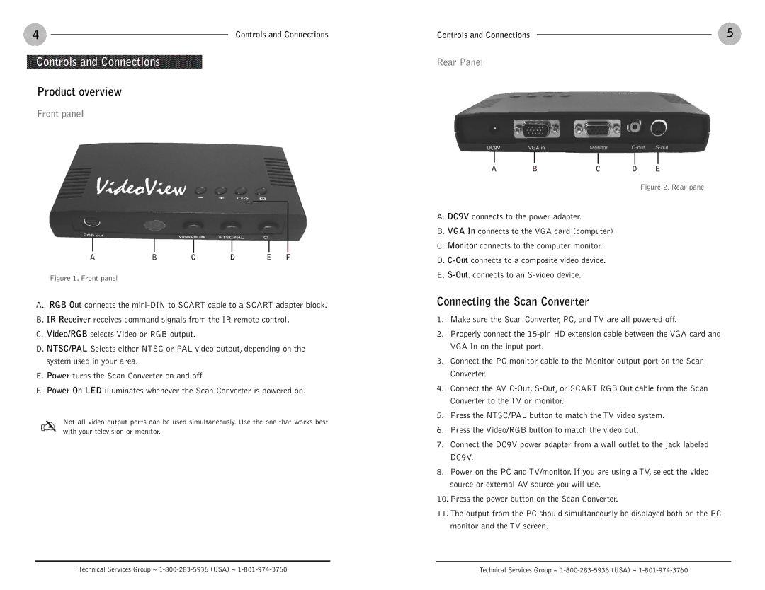
Rear Panel
A BC D E
Figure 2. Rear panel
A. DC9V connects to the power adapter.
B. VGA In connects to the VGA card (computer)
C. Monitor connects to the computer monitor.
D.
E.
Connecting the Scan Converter
1.Make sure the Scan Converter, PC, and TV are all powered off.
2.Properly connect the
3.Connect the PC monitor cable to the Monitor output port on the Scan Converter.
4.Connect the AV
5.Press the NTSC/PAL button to match the TV video system.
6.Press the Video/RGB button to match the video out.
7.Connect the DC9V power adapter from a wall outlet to the jack labeled DC9V.
8.Power on the PC and TV/monitor. If you are using a TV, select the video source or external AV source you will use.
10.Press the power button on the Scan Converter.
11.The output from the PC should simultaneously be displayed both on the PC monitor and the TV screen.
Technical Services Group ~ | Technical Services Group ~ |