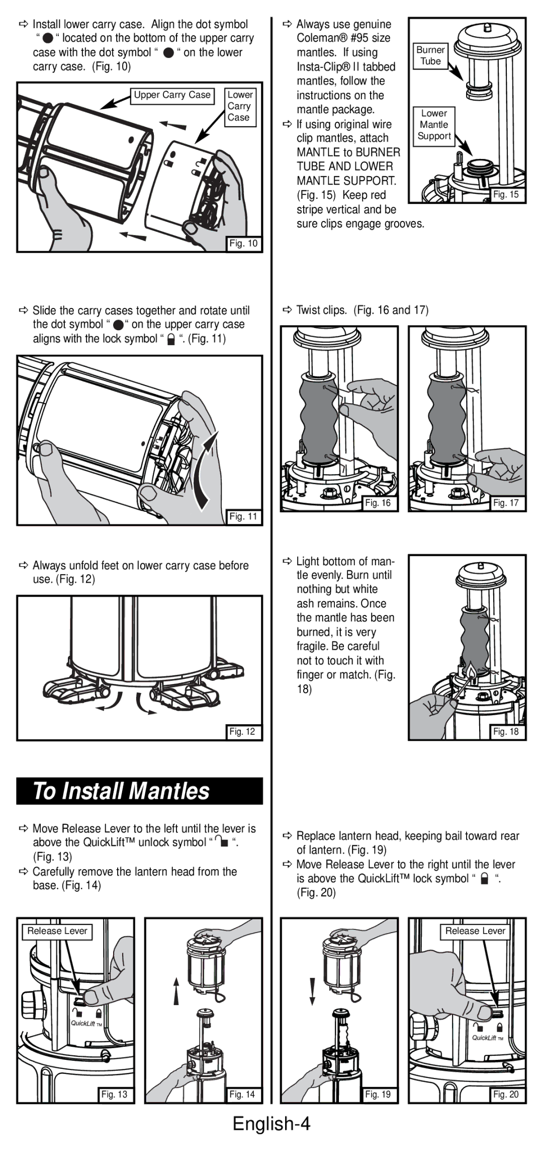
DInstall lower carry case. Align the dot symbol
““ located on the bottom of the upper carry
case with the dot symbol “![]() “ on the lower carry case. (Fig. 10)
“ on the lower carry case. (Fig. 10)
Upper Carry Case | Lower |
| Carry |
| Case |
| Fig. 10 |
D Slide the carry cases together and rotate until |
the dot symbol “ “ on the upper carry case |
DAlways use genuine Coleman® #95 size
mantles. If using | Burner | |
Tube | ||
| ||
mantles, follow the |
| |
instructions on the |
| |
mantle package. | Lower | |
D If using original wire | ||
Mantle | ||
clip mantles, attach | Support | |
MANTLE to BURNER |
| |
TUBE AND LOWER |
| |
MANTLE SUPPORT. |
| |
(Fig. 15) Keep red | Fig. 15 |
stripe vertical and be
sure clips engage grooves.
D Twist clips. (Fig. 16 and 17)
aligns with the lock symbol “ “. (Fig. 11)
Fig. 11 |
DAlways unfold feet on lower carry case before use. (Fig. 12)
Fig. 12 |
To Install Mantles
Fig. 16 |
DLight bottom of man- tle evenly. Burn until nothing but white ash remains. Once the mantle has been burned, it is very fragile. Be careful not to touch it with finger or match. (Fig. 18)
Fig. 17 |
Fig. 18 |
DMove Release Lever to the left until the lever is above the QuickLift™ unlock symbol “![]()
![]() “. (Fig. 13)
“. (Fig. 13)
DCarefully remove the lantern head from the base. (Fig. 14)
DReplace lantern head, keeping bail toward rear of lantern. (Fig. 19)
DMove Release Lever to the right until the lever is above the QuickLift™ lock symbol “ ![]() “. (Fig. 20)
“. (Fig. 20)
Release Lever |
Fig. 13 |
Fig. 14 |
Fig. 19 |
Release Lever |
Fig. 20 |