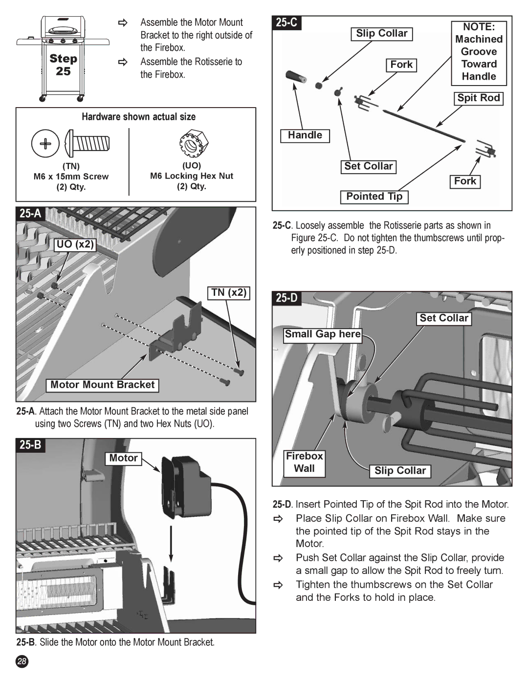
| Ö | Assemble the Motor Mount |
|
| Bracket to the right outside of |
Step |
| the Firebox. |
Ö | Assemble the Rotisserie to | |
25 |
| the Firebox. |
Hardware shown actual size
(TN) | (UO) |
M6 x 15mm Screw | M6 Locking Hex Nut |
(2) Qty. | (2) Qty. |
|
|
|
UO (x2) |
TN (x2) |
Motor Mount Bracket |
25-B
Motor![]()
| NOTE: | |
Slip Collar | ||
Machined | ||
| ||
| Groove | |
Fork | Toward | |
| Handle | |
| Spit Rod | |
Handle |
| |
Set Collar |
| |
| Fork | |
Pointed Tip |
|
|
|
| Set Collar |
Small Gap here |
|
Firebox |
|
Wall | Slip Collar |
ÖPlace Slip Collar on Firebox Wall. Make sure the pointed tip of the Spit Rod stays in the Motor.
ÖPush Set Collar against the Slip Collar, provide a small gap to allow the Spit Rod to freely turn.
ÖTighten the thumbscrews on the Set Collar and the Forks to hold in place.
28
