Compaq M-LVDS manual PS1 PS2 PS3, Recommended Equipment

Models: M-LVDS

1 32
Download 32 pages 58.51 Kb
Page 16
Image 16

Recommended Equipment

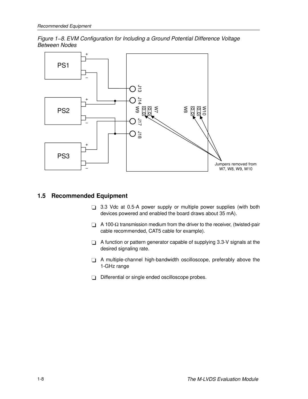
Figure 1−8. EVM Configuration for Including a Ground Potential Difference Voltage Between Nodes

PS1

PS2

PS3

+

+

+

J13


J14


W9

W7

W8

J17


J18


W10

Jumpers removed from

W7, W8, W9, W10

1.5Recommended Equipment

-3.3 Vdc at 0.5-A power supply or multiple power supplies (with both devices powered and enabled the board draws about 35 mA).

-A 100-transmission medium from the driver to the receiver, (twisted-pair cable recommended, CAT5 cable for example).

-A function or pattern generator capable of supplying 3.3-V signals at the desired signaling rate.

-A multiple-channel high-bandwidth oscilloscope, preferably above the 1-GHz range

-Differential or single ended oscilloscope probes.

1-8

The M-LVDS Evaluation Module

Page 16
Image 16
Compaq M-LVDS manual PS1 PS2 PS3, Recommended Equipment