Typical Cable Test Configurations
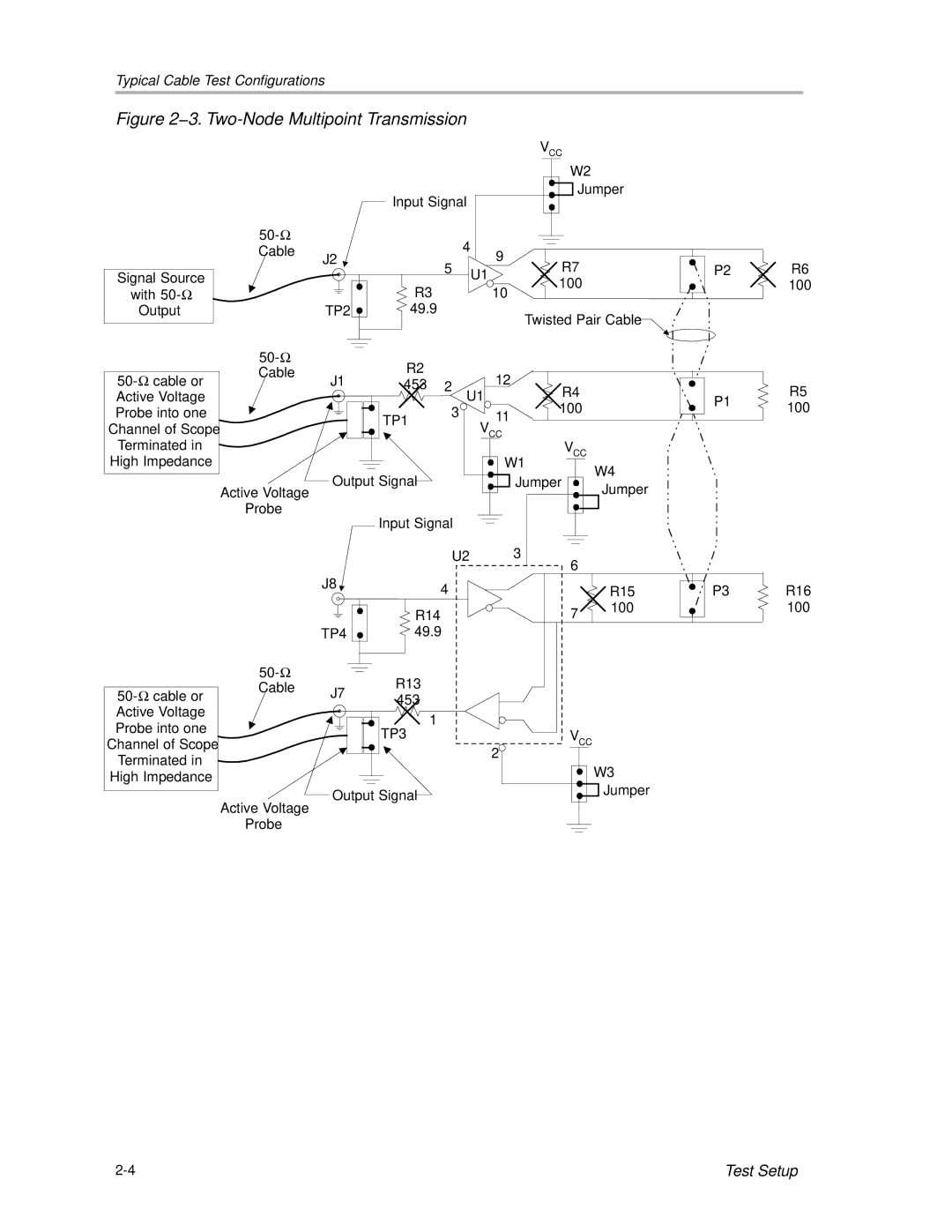
Figure 2−3. Two-Node Multipoint Transmission
VCC
Signal Source
with
Output
Cable
J2
TP2 ![]()
W2
Jumper
Input Signal
| 4 | 9 |
5 |
| |
U1 | R7 | |
| 100 | |
R3 |
| |
| 10 | |
49.9 |
|
|
Twisted Pair Cable
P2
R6
100
|
| R2 |
|
|
|
| |
Cable | J1 |
| 12 |
|
| ||
| 453 | 2 U1 | R4 |
| |||
Active Voltage |
|
|
|
| P1 | ||
Probe into one |
|
|
| 3 | 11 | 100 | |
|
| TP1 |
| ||||
|
|
|
| ||||
Channel of Scope |
|
| VCC |
|
| ||
Terminated in |
|
|
|
|
| VCC |
|
High Impedance |
|
|
|
| W1 | W4 | |
|
| Output Signal |
|
| Jumper | ||
| Active Voltage |
|
| Jumper | |||
|
|
|
|
|
| ||
| Probe |
| Input Signal |
|
|
| |
|
|
|
|
|
| ||
|
|
|
| U2 |
| 3 |
|
|
|
|
|
|
| 6 |
|
R5
100
|
| J8 | 4 |
|
|
| |
|
|
| R14 |
|
| TP4 | 49.9 |
|
| R13 | |
Cable | J7 | ||
| 453 | ||
Active Voltage |
|
| 1 |
Probe into one |
|
| |
|
| TP3 | |
Channel of Scope |
|
| |
|
| 2 | |
Terminated in |
|
| |
|
|
| |
High Impedance |
|
|
|
| Active Voltage | Output Signal | |
|
|
| |
| Probe |
|
|
| R15 | P3 |
7 | 100 |
|
|
|
VCC
W3
Jumper
R16
100
Test Setup |