Typical Cable Test Configurations
2.1.2Point-to-Point Parallel Terminated Simplex Transmission
1)Connect a
2)Verify resistor R4 and R7 are installed.
3)Remove resistors R5 and R6. This properly terminates the transmission line at both ends.
4)Enable the driver by connecting the jumper on W2 between pin 1 and pin 2, or U1 pin 4 to VCC.
5)Enable the receiver by connecting the jumper on W1 between pin 2 and pin 3, or U1 pin 3 to GND.
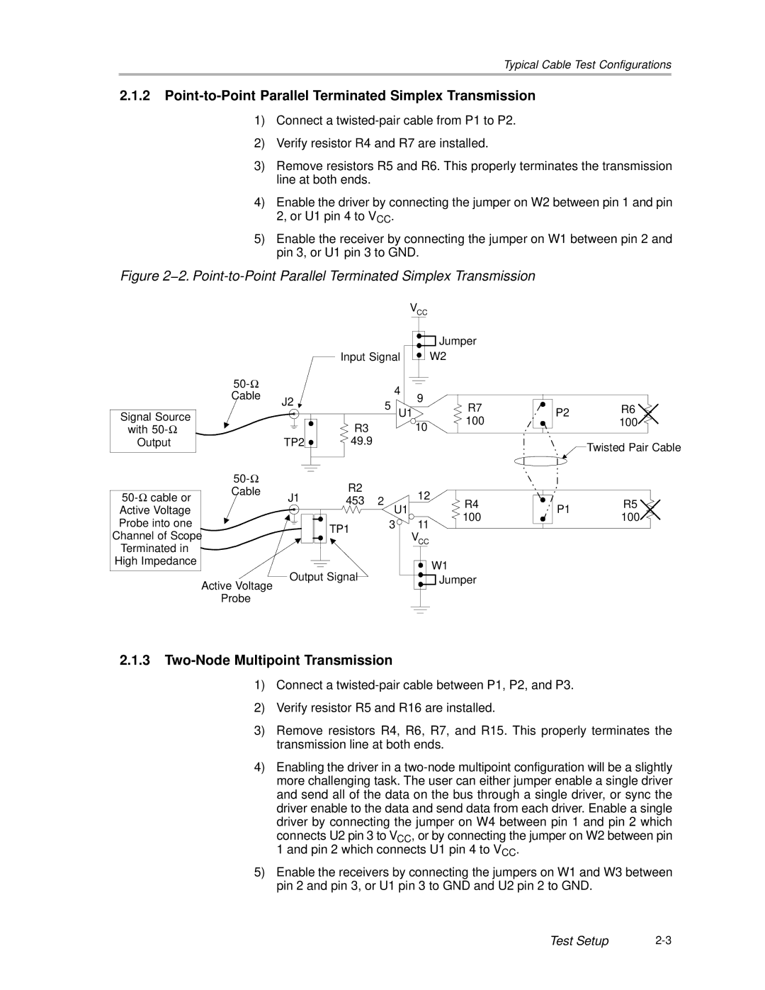
Figure 2−2. Point-to-Point Parallel Terminated Simplex Transmission
VCC
Signal Source
with
Output
Cable
J2
TP2 ![]()
|
| Jumper |
|
|
Input Signal |
| W2 |
|
|
4 | 9 |
|
|
|
5 | R7 |
| R6 | |
| P2 | |||
U1 |
| 100 | 100 | |
R3 | 10 |
| ||
|
|
| ||
49.9 |
|
|
| Twisted Pair Cable |
|
|
|
|
|
|
|
| R2 |
|
| ||
50- | Ω | cable or | Cable | J1 |
| 12 | ||
453 | 2 | |||||||
| ||||||||
|
| R4 | ||||||
Active Voltage |
|
|
| U1 | 100 | |||
Probe into one |
|
|
| 3 | ||||
|
| TP1 | 11 | |||||
Channel of Scope |
|
| VCC | |||||
|
|
| ||||||
Terminated in |
|
|
|
|
| |||
High Impedance |
|
|
|
| W1 | |||
|
|
|
| Output Signal |
| |||
|
|
| Active Voltage |
| Jumper | |||
|
|
|
|
|
|
| ||
|
|
| Probe |
|
|
|
| |
P1 | R5 | |
100 | ||
|
2.1.3Two-Node Multipoint Transmission
1)Connect a
2)Verify resistor R5 and R16 are installed.
3)Remove resistors R4, R6, R7, and R15. This properly terminates the transmission line at both ends.
4)Enabling the driver in a
connects U2 pin 3 to VCC, or by connecting the jumper on W2 between pin 1 and pin 2 which connects U1 pin 4 to VCC.
5)Enable the receivers by connecting the jumpers on W1 and W3 between pin 2 and pin 3, or U1 pin 3 to GND and U2 pin 2 to GND.
Test Setup |