MPAC-18
OPERATING AND SERVICE MANUAL
Page
Copyright
TRADEMARKS
COPYRIGHTS
Preliminary Release
REVISION HISTORY
Preliminary Release
Preliminary Release
FEATURE SUMMARY
TABLE OF CONTENTS
I/O FEATURES
INSTALLATION GUIDELINES
Table 1 Unit Specifcations
Power Jack
TABLES
Table 2 Keyboard Jack
INTRODUCTION
I/O features
Interchangeable terms
Page
Warnings, Cautions, and Notes as Used in this Publication
Feature
Feature Summary
Standard Features & I/O
Description
Grounding
Installation Guidelines
General
Bulkhead Mounting
Clearances
System Startup
Power-up and Software Installation
Installation
13. You will be prompted for a password Login Recommendation
Configuring the Military Computer to Run on a Microsoft Network
MPAC-18 Manual
4. To modify the TCP/IP properties
Page
Copyright March 2003, Computer Dynamics, Inc All Rights Reserved
B. In the Microsoft TCP/IP Properties, change the Address from 111.111.111.111 to a unique address and change the subnet mask from 255.0.0.0 to your subnet mask. If your networks IP addresses are controlled by a DHCP server, change the setting from Specify an IP address to Obtain an IP address from a DHCP Server
5. To add other protocols such as NetBEUI, on the Protocols tab of the Network dialog box, click Add. A list of available protocols will appear. Choose the protocol you wish to install and click OK. The system may ask where the Windows Setup files are located. They are in the C\I386\ directory
Copyright March 2003, Computer Dynamics, Inc All Rights Reserved
Page
MPAC-18 Manual
Hardware
Installing Application Software
Power Supply Section
TFT Graphic Display System
Circuit Breaker and ATX Switch
Single Board Computer SBCP3/133
Touch Screen
Keyboard/Mouse Port
Power Input
USB Ports
Floppy & CD-ROM
Printer Port LPT-1
Serial Communication Ports
Network
Installed Network Components
Networking Communications
Comments
BIOS Settings
Diagnostics and Troubleshooting
Self-Test Diagnostics
Troubleshooting Power-up
Maintenance
External PS/2 Mouse
Display
Memory
Keyboard
Symptom
Network Communications
Printing
Solution
Page
Figure 1. Front Plan View Figure 2. Bottom Plan View
See the Appendix for I/O panel layout
MPAC-18 Manual
MPAC-18 Manual
Figure 3. Side Plan View Figure 4. Top Plan View
Page
Copyright March 2003, Computer Dynamics, Inc All Rights Reserved
MPAC-18 Manual
Figure 5. Back Plan View
Page
Copyright March 2003, Computer Dynamics, Inc All Rights Reserved
MPAC-18 Manual
Figure 6. Installation Diagram
Page
Copyright March 2003, Computer Dynamics, Inc All Rights Reserved
Specifications
Table 1 Unit Specifcations
VIDEO INTERFACE
Vertical Connectors and Strapping Fields
Figure 7. Pin configuration
1 2 3 4
MPAC-18 Manual
Appendix I/O
Page
Copyright March 2003, Computer Dynamics, Inc All Rights Reserved
Page
I/O Layout and Pinout Configuration Figure 8. I/O Panel
INSERT PICTURE AFTER FIRST BUILD
MPAC-18 Manual
Table 3 Parallel LPT-1 Jack
Table 2 Keyboard Jack
Table 6 USB Jack
Table 5 Power Jack
Table 4 Ethernet Jacks
Name
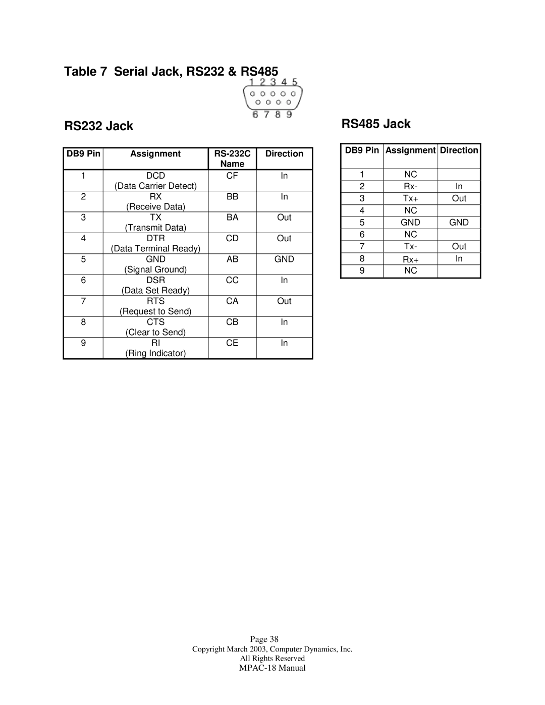
Table 7 Serial Jack, RS232 & RS485 RS232 Jack
RS485 Jack
ADDITIONAL READING
COMPUTER DYNAMICS INCORPORATED 7640 Pelham Rd., Greenville, SC