Removal and Replacement Procedures
❏Audio board (Section 5.15)
❏USB/power connector board (Section 5.18)
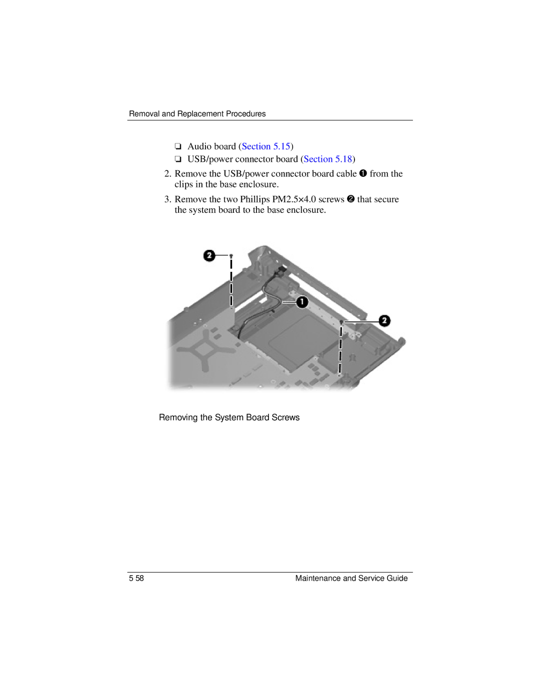
2.Remove the USB/power connector board cable 1 from the clips in the base enclosure.
3.Remove the two Phillips PM2.5×4.0 screws 2 that secure the system board to the base enclosure.
Removing the System Board Screws
Maintenance and Service Guide |