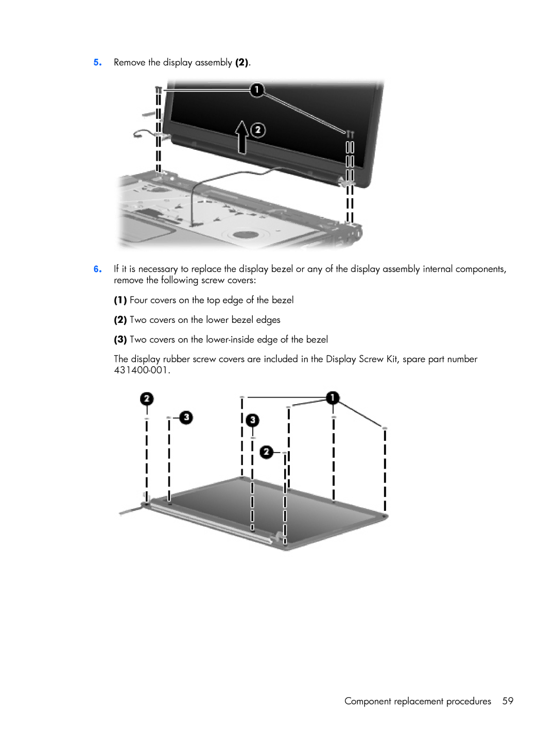
5. Remove the display assembly (2).
6. If it is necessary to replace the display bezel or any of the display assembly internal components, remove the following screw covers:
(1)Four covers on the top edge of the bezel
(2)Two covers on the lower bezel edges
(3)Two covers on the
The display rubber screw covers are included in the Display Screw Kit, spare part number
Component replacement procedures 59