16. Remove the display hinges (2). The display hinges are available using spare part number
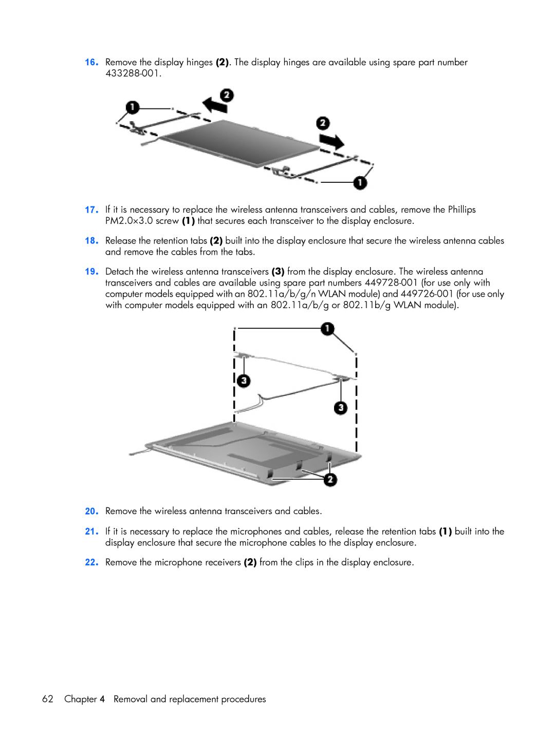
17. If it is necessary to replace the wireless antenna transceivers and cables, remove the Phillips PM2.0×3.0 screw (1) that secures each transceiver to the display enclosure.
18. Release the retention tabs (2) built into the display enclosure that secure the wireless antenna cables and remove the cables from the tabs.
19. Detach the wireless antenna transceivers (3) from the display enclosure. The wireless antenna transceivers and cables are available using spare part numbers
20. Remove the wireless antenna transceivers and cables.
21. If it is necessary to replace the microphones and cables, release the retention tabs (1) built into the display enclosure that secure the microphone cables to the display enclosure.
22. Remove the microphone receivers (2) from the clips in the display enclosure.
62 Chapter 4 Removal and replacement procedures