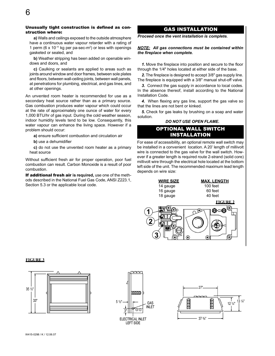
CVF36N, CVF36P specifications
The Continental CVF36P and CVF36N are innovative air-cooled engines known for their reliability, performance, and versatility, making them popular choices in various aviation applications. These models are designed to deliver enhanced power, efficiency, and durability, meeting the demands of both recreational and commercial pilots.One of the standout features of the CVF36P and CVF36N is their robust power output. These engines are designed to produce approximately 36 horsepower, enabling aircraft to achieve impressive climb rates and cruise speeds. The engines incorporate advanced engineering principles that ensure optimal performance, contributing to a smooth and responsive flying experience.
In terms of technology, the CVF36 series utilizes a four-cylinder, horizontally opposed configuration. This design not only helps in reducing vibration but also contributes to a lower center of gravity, enhancing aircraft stability during flight. The engines are equipped with a dual ignition system, ensuring reliability and redundancy that are critical in aviation. This dual ignition setup helps in maintaining engine operation even if one of the spark plugs fails, thereby enhancing safety.
The CVF36P variant is recognized for its premium performance in various operating conditions. It features a precision-engineered crankshaft and an efficient cooling system that prevents overheating. As a result, this engine is suitable for a wide range of applications, from light sport aircraft to experimental models.
On the other hand, the CVF36N variant focuses on delivering superior fuel efficiency. It is designed with advanced aerodynamics and engine management systems that optimize fuel consumption without compromising power output. This characteristic makes the CVF36N particularly appealing to budget-conscious pilots looking for long-range flying capabilities.
Both engines come with a range of customizable options, allowing builders and aircraft manufacturers to tailor them according to specific needs. This flexibility, combined with a strong support network and comprehensive service options, ensures that owners can maintain peak performance throughout the life of the engine.
Overall, the Continental CVF36P and CVF36N engines represent a significant advancement in aviation technology, offering a blend of power, efficiency, and reliability. As pilots continue to seek engines that meet stringent performance and safety standards, these models stand out as exemplary choices in the growing market of light aircraft engines.

