Manuals
/
Country Home Products
/
Lawn and Garden
/
Tiller
Country Home Products
ROTO-HOGTM manual Schematic Diagram - Main Assembly, 070718
Models:
ROTO-HOGTM
1
45
54
54
Download
54 pages
48.43 Kb
42
43
44
45
46
47
48
49
<
>
Troubleshooting
Specification
Install
Parts list
Schematic Diagram - Main Assembly
Warranty
Maintenance
Extra Wire
Setting Up Your Dr Roto-Hogpower Tiller
⇒Check the oil level and adjust as needed
Page 45
Image 45
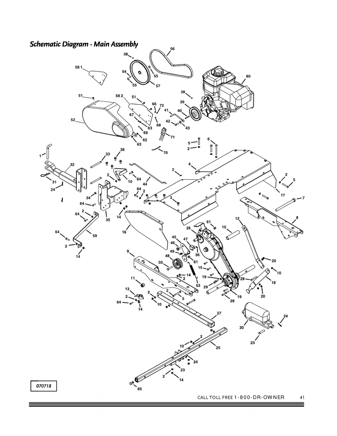
Schematic Diagram - Main Assembly
070718
CALL TOLL FREE
1-800-DR-OWNER
41
Page 44
Page 46
Page 45
Image 45
Page 44
Page 46
Contents
SAFETY & OPERATING INSTRUCTIONS
DR ROTO-HOGPOWER TILLER
Thanks once again for all of us at
Table of Contents
PARTS LISTS, SCHEMATIC DIAGRAMS AND WARRANTY
CHAPTER
INTRODUCING THE DR ROTO-HOGPOWER TILLER
Conventions used in this manual
NOTE: This information may be helpful to you
DR ROTO-HOGPOWER TILLER Specification Sheet
GENERAL SAFETY RULES
Labels
CHAPTER
4 DR ROTO-HOGPOWER TILLER
CALL TOLL-FREE 1-800-DR-OWNER
Protecting Yourself and Those Around You
Slope Operation
Safety for Children
CALL TOLL-FREE 1-800-DR-OWNER
Safety with Gasoline-PoweredMachines
8 DR ROTO-HOGPOWER TILLER
General Safety
A Note to All Users
Additional Information and Potential Changes
CALL TOLL-FREE 1-800-DR-OWNER
10 DR ROTO-HOGPOWER TILLER
SETTING UP YOUR DR ROTO-HOGPOWER TILLER
CHAPTER
1-800-DR-OWNER
Manual Recoil Start Handle Battery Oil Fill
DR ROTO-HOGPOWER TILLER Controls and Features
OPTIONAL Spreader ON-OFFSwitch
Electric-StarterSwitch Control Box
Opening the Shipping Carton
Unpacking and Assembling the Machine
4 Pins
Fuse Location in Front of Battery
Negative
Terminal
Figure Push to lower the unit raise the Axles
Axle Hold Down Brackets
Figure Valve Stem
Cotter Pin Legs
Charging the Battery
About the Battery
Extra Wire
2.Plug the Charger into a standard wall outlet
Charging the Battery
Capacities
Adding the Engine Oil and Gasoline
Choke
Air Filter
Fuel Shut-Off Throttle Recoil Starter Handle
Oil Fill
up or down. The lower the front of the
Attaching the DR ROTO-HOGPOWER TILLER Control Box
frame, the deeper the Tine depth for
entering the Tines during
OPERATING YOUR DR ROTO-HOGPOWER TILLER
Operator Controls
CHAPTER
Manual Starting
Before Starting the Engine
Electric Starting
Stopping the Engine
Starter Key Switch Figure
24 DR ROTO-HOGPOWER TILLER
Operating Safety
Understanding the Control Box
U-Bolt*for Hanging the Control Box
Figure
Operating Parameters
Operating Procedures
Food Plot Installation and Sod Busting
Gardens
Cultivating Tips
Tilling Tips
Slopes and Uneven Terrain
Handling and Transporting
28 DR ROTO-HOGPOWER TILLER
Regular Maintenance Checklist
MAINTAINING THE DR ROTO-HOGPOWER TILLER
NOTE: 1st time 5 hrs
Procedure
Lubrication
Removing and Replacing the Engine Oil
Charging the Battery
Battery Care
Recycling a Used Battery
Disposing of the Battery Responsibly
Removing and Replacing the V-Belt
Tine Operation Check
Tine Shear Pins
End of Season and Storage
Troubleshooting Table
TROUBLESHOOTING
Recoil will not pull out or is difficult to pull
CHAPTER
The Engine lacks power or is not running smoothly
The Engine will not start using Electric- Start
Engine smokes
The Engine runs well but labors when tilling
The Engine runs well but the Tines won’t move
⇒Check the oil level and adjust as needed
PARTS LISTS, SCHEMATIC DIAGRAMS AND WARRANTY
Parts List - Main Assembly
CHAPTER
Schematic Diagram - Main Assembly
070718
CALL TOLL FREE 1-800-DR-OWNER
Parts List -TineDrive Transmission Assembly
Ref# Part#
Description
CALL TOLL FREE 1-800-DR-OWNER
070718
Parts List - Axle Assembly
Schematic Diagram - Axle Assembly
070718
CALL TOLL FREE 1-800-DR-OWNER
Wiring Diagram - Manual Start model
46 DR ROTO-HOGPOWER TILLER
070725
Wiring Diagram - Electric-Startmodel
070725
CALL TOLL FREE 1-800-DR-OWNER
48 DR ROTO-HOGPOWER TILLER
Notes
Customer Service Hotline
DR ROTO-HOG POWER TILLER
Terms and Conditions
2-YearLimited Warranty
Quick Tilling Tips
Daily Checklist for the DR ROTO-HOGPOWER TILLER