CPG #2561255 | FIRELARM 2500 Operating Manual |
A.4 Master Box Module (Model MBM)
Contents
1
UL LISTED: For use with the FireLarm 2500 Part No.
Power requirements:
Standby: 30mA Max @24VDC
Alarm: 300 mA Max @24VCD Master Box Coil Resistance: 14.5 ohms
Trouble output: Positive 2.5 V goes low in trouble and SPDT contacts transfer. Contacts rated 2A@30VDC
Visual indicators: Yellow - Trouble/Disable
Yellow - Reset supervisory/ contacts off normal Disable capability: Switch provided (can be made inoperative) Size:
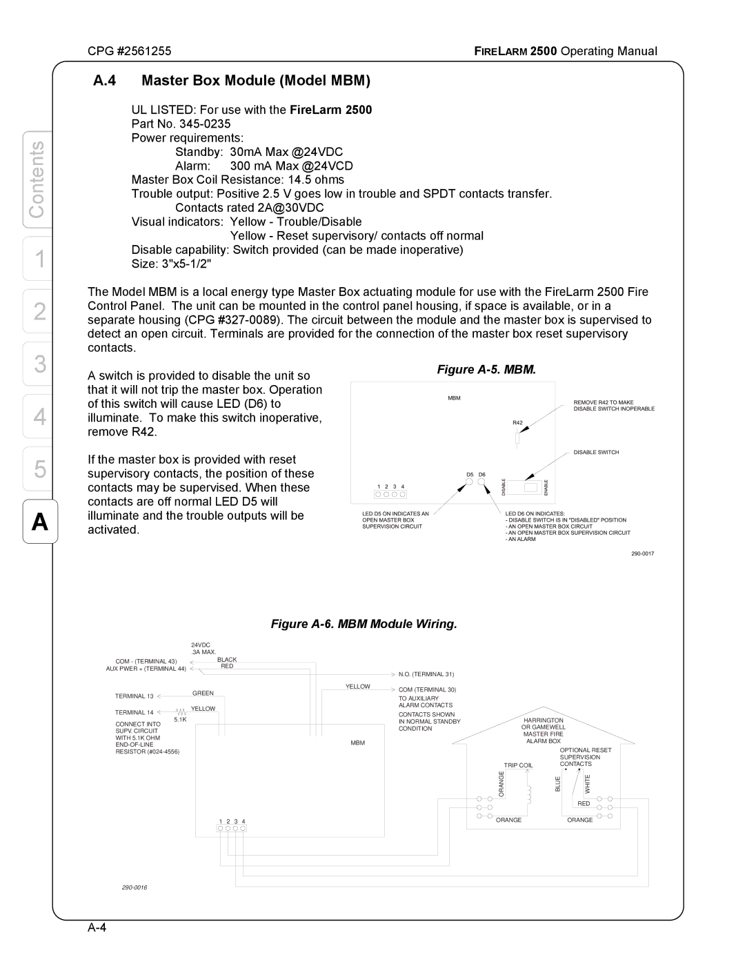
2 | The Model MBM is a local energy type Master Box actuating module for use with the FireLarm 2500 Fire | |||||||||||||||||||||||
Control Panel. The unit can be mounted in the control panel housing, if space is available, or in a | ||||||||||||||||||||||||
separate housing (CPG | ||||||||||||||||||||||||
| detect an open circuit. Terminals are provided for the connection of the master box reset supervisory | |||||||||||||||||||||||
3 | contacts. |
|
|
|
|
|
|
|
|
|
|
|
|
|
|
|
|
|
|
|
|
|
|
|
A switch is provided to disable the unit so |
|
|
|
|
|
| Figure | |||||||||||||||||
|
|
|
|
|
|
|
|
|
|
|
|
|
|
|
|
|
|
|
|
|
|
| ||
| that it will not trip the master box. Operation |
|
|
|
|
|
|
|
|
|
|
|
|
|
|
|
|
|
|
|
|
|
|
|
4 | of this switch will cause LED (D6) to |
|
|
|
|
|
|
|
|
|
|
|
|
|
|
|
|
|
|
|
|
|
|
|
|
|
|
|
|
|
|
|
|
|
|
|
|
|
|
|
|
|
|
|
|
|
| ||
illuminate. To make this switch inoperative, |
|
|
|
|
|
|
|
|
|
|
|
|
|
|
|
|
|
|
|
|
|
|
| |
| remove R42. |
|
|
|
|
|
|
|
|
|
|
|
|
|
|
|
|
|
|
|
|
|
|
|
5 | If the master box is provided with reset |
|
|
|
|
|
|
|
|
|
|
|
|
|
|
|
|
|
|
|
|
|
|
|
|
|
|
|
|
|
|
|
|
|
|
|
|
|
|
|
|
|
|
|
|
|
| ||
|
|
|
|
|
|
|
|
|
|
|
|
|
|
|
|
|
|
|
|
|
|
| ||
supervisory contacts, the position of these |
|
|
|
|
|
|
|
|
|
|
|
|
|
|
|
|
|
|
|
|
|
|
| |
| contacts may be supervised. When these |
|
|
|
|
|
|
|
|
|
|
|
|
|
|
|
|
|
|
|
|
|
|
|
A | contacts are off normal LED D5 will |
|
|
|
|
|
|
|
|
|
|
|
|
|
|
|
|
|
|
|
|
|
|
|
illuminate and the trouble outputs will be |
|
|
|
|
|
|
|
|
|
|
|
|
|
|
|
|
|
|
|
|
|
|
| |
|
|
|
|
|
|
|
|
|
|
|
|
|
|
|
|
|
|
|
|
|
|
| ||
|
|
|
|
|
|
|
|
|
|
|
|
|
|
|
|
|
|
|
|
|
|
| ||
|
|
|
|
|
|
|
|
|
|
|
|
|
|
|
|
|
|
|
|
|
|
| ||
activated. |
|
|
|
|
|
|
|
|
|
|
|
|
|
|
|
|
|
|
|
|
|
|
| |
|
|
|
|
|
|
|
|
|
|
|
|
|
|
|
|
|
|
|
|
|
|
| ||
|
|
|
|
|
|
|
|
|
|
|
|
|
|
|
|
|
|
|
|
|
|
| ||
|
|
|
|
|
|
|
|
|
|
|
|
|
|
|
|
|
|
|
|
|
|
| ||
|
|
|
|
|
|
|
|
|
|
|
|
|
|
|
|
|
|
|
|
|
|
|
|
|
COM - (TERMINAL 43)
AUX PWER + (TERMINAL 44)
TERMINAL 13
TERMINAL 14
5.1K
CONNECT INTO
SUPV. CIRCUIT
WITH 5.1K OHM
24VDC
.3A MAX.
BLACK
RED
GREEN
YELLOW
Figure A-6. MBM Module Wiring.
| N.O. (TERMINAL 31) |
|
|
YELLOW | COM (TERMINAL 30) |
|
|
|
|
| |
| TO AUXILIARY |
|
|
| ALARM CONTACTS |
|
|
| CONTACTS SHOWN | HARRINGTON | |
| IN NORMAL STANDBY | ||
| CONDITION | OR GAMEWELL | |
|
| MASTER FIRE | |
MBM |
| ALARM BOX | |
|
|
| |
|
|
| OPTIONAL RESET |
|
|
| SUPERVISION |
|
| TRIP COIL | CONTACTS |
| ORANGE | BLUE | WHITE |
|
|
| RED |
1 2 3 4 | ORANGE | ORANGE |
