90°(0°)Stop
1.Disconnectthesawfromthepowersource.
2.Turnthebladeelevationhandwheelandraisethe bladetothemaximumelevation.
3.Loosenthebladebevellockknob(1)andmovethe
bladetothemaximumverticalposition,thentighten thelockknob(1).
4.Placeacombinationsquareonthetableandagainst theblade(2)todetermineif thebladeis90°(0°)to thetable.(Fig.P)
5.tfthebladeisnot90°(0°)tothetable,loosenthetwo setscrews(4),locatedon thecollar(5)underneath thetablesaw(Fig.Q)withthehexkey(Carton ContentsJ)andbackoffthecollar.
6.Loosenthebevellockknob,turnthebladetilting handwheelto movethebladeuntilitis90°(0°)tothe tableandtightenthebevellockknob.
7.Adjustthecollar(5)soitcontactsthebracket(3)
whenthebladeis90°(0°)tothetable.Tightenthe twosetscrews(4)(Fig.Q).
Fig.O
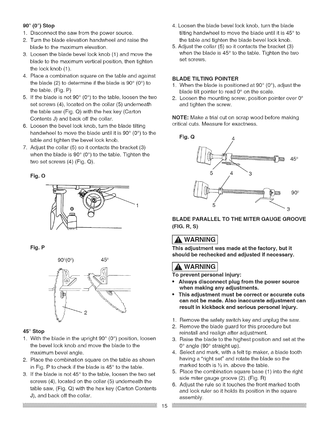
Fig.P
900(00) 450
45°Stop
1.Withthebladeintheupright90°(0°)position,loosen thebevellockknobandmovethebladetothe maximumbevelangle.
2.Placethecombinationsquareonthetableasshown in Fig.Ptocheckif thebladeis45°tothetable.
3.tfthebladeisnot45°tothetable,loosenthetwoset
screws(4),locatedonthecollar(5)underneaththe
tablesaw,(Fig.Q)withthehexkey(CartonContents
J),andbackoffthecollar.
4.Loosenthebladebevellockknob,turntheblade tiltinghandwheeltomovethebladeuntilit is45°to thetableandtightenthebladebevellockknob.
5.Adjustthecollar(5)soitcontactsthebracket(3)
whenthebladeis45°tothetable.Tightenthetwo
setscrews.
BLADETiLTiNGPOINTER
1.Whenthebladeispositionedat90°(0°),adjustthe bladetiltpointerto read0°onthescale.
2.Loosenthemountingscrew,positionpointerover0°
andtightenthescrew.
NOTE:Makeatrialcutonscrapwoodbeforemaking
criticalcuts.Measureforexactness.
Fig.Q4
450
90o
3
BLADEPARALLELTOTHEMITERGAUGEGROOVE (FIG.R,S)
IA WARNING!
This adjustment was made at the factory, but it should be rechecked and adjusted if necessary.
],A WARNING]
To prevent personal injury:
=Always disconnect plug from the power source when making any adjustments.
•This adjustment must be correct or accurate cuts can not be made. Also inaccurate adjustment can result in kickback and serious personal injury.
1.Remove the safety switch key and unplug the saw.
2. Remove the blade guard for this procedure but reinstall and realign after adjustment.
3. Raise the blade to the highest position and set at the 0° angle (90 ° straight up).
4. Select and mark, with a felt tip maker, a blade tooth having a "right set" and rotate the blade so the marked tooth is Y2in. above the table.
5. Place the combination square base (1) into the right side miter gauge groove (2). (Fig. R)
6. Adjust the rule so it touches the front marked tooth and lock ruler so it holds its position in the square assembly.
15