7.Whenthesplitterisproperlyalignedwiththesaw blade,tightentheboltsecurely.
NOTE:The splitter bracket must always be
correctly aligned so the cut workpiece will pass on either side without binding or twisting,
[A WARNINa
See Fig.
Fig,
AVOID KICKBACKS (FIG. J)
(Work thrown back towards you) by keeping the blade sharp, the rip fence parallel to the saw blade and by keeping the splitter,
[,A WARNING I
Improper splitter alignment can cause "kickback"
and serious injury.
Fig, J | Pawl | 8 | 10 |
|
|
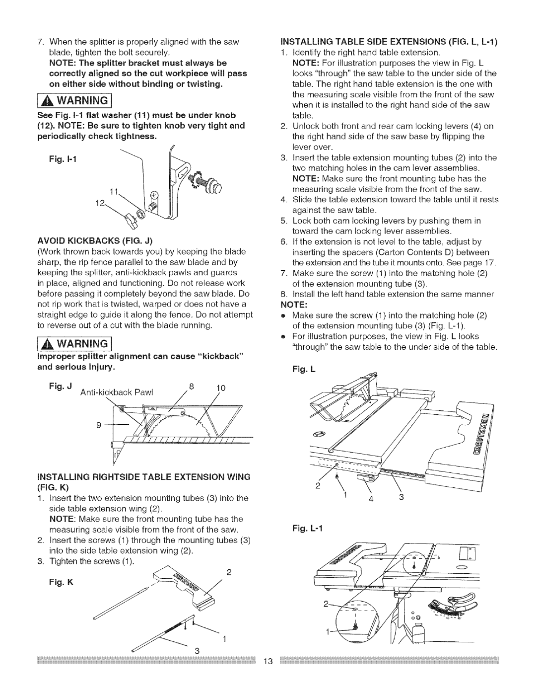
INSTALLING TABLE SIDE EXTENSIONS (FIG. L, L=I)
1.Identify the right hand table extension.
NOTE: For illustration purposes the view in Fig. L looks "through" the saw table to the under side of the table. The right hand table extension is the one with the measuring scale visible from the front of the saw when it is installed to the right hand side of the saw table.
2.Unlock both front and rear cam locking levers (4) on the right hand side of the saw base by flipping the lever over.
3.Insert the table extension mounting tubes (2) into the two matching holes in the cam lever assemblies. NOTE: Make sure the front mounting tube has the measuring scale visible from the front of the saw.
4.Slide the table extension toward the table until it rests against the saw table.
5.Lock both cam locking levers by pushing them in toward the cam locking lever assemblies.
6.tf the extension is not level to the table, adjust by inserting the spacers (Carton Contents D) between the extension and the tube it mounts onto. See page 17.
7.Make sure the screw (1) into the matching hole (2) of the extension mounting tube (3).
8.Install the left hand table extension the same manner NOTE:
• Make sure the screw (1) into the matching hole (2) of the extension mounting tube (3) (Fig.
• For illustration purposes, the view in Fig. L looks "through" the saw table to the under side of the table.
Fig, L
INSTALLING RIGHTSIDE TABLE EXTENSION WING (FIG. K)
1.Insert the two extension mounting tubes (3) into the side table extension wing (2).
NOTE: Make sure the front mounting tube has the measuring scale visible from the front of the saw.
2.Insert the screws (1) through the mounting tubes (3) into the side table extension wing (2).
3.Tighten the screws (1).
Fig. K | z_ | 2 |
3
2 \
1 4 3
Fig. L=I
13